How do you calculate the values of R1 and R2 in the circuit for a Bidirectional Logic Level Shifter if the high and low voltages are known?
Searching on the Internet I found 10K is a good option to start with but how is this derived?

How do you calculate the values of R1 and R2 in the circuit for a Bidirectional Logic Level Shifter if the high and low voltages are known?
Searching on the Internet I found 10K is a good option to start with but how is this derived?
The resistor values need to be chosen based on the rise time constraints. Lower the resistor, lower the rise time. However, a low value of resistor will increase VOL. So, you have to choose a resistor such that it meets the rise time and VOL specifications.
If this unit is to facilitate communications in both directions, then both resistors are required, but I suspect that you might only need this for the direction [5V or 3.3V or 0V in] --> [24V or 0V out], and the 3.3V/5V input comes from a microcontroller output. If that's the case, then the microcontroller output is a push/pull type, which will do the "pulling up" for you, and you won't need R1:
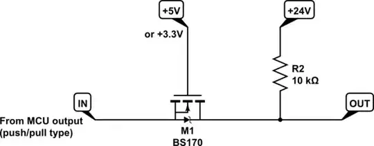
simulate this circuit – Schematic created using CircuitLab
Another example of a system which may not need require R1, is an \$I^2C\$ bus, where R1 is actually already installed elsewhere along the bus, typically 4.7kΩ, and which is already pulling the line high.
If there isn't any other element doing the "pulling-up" on the 3.3V side (for instance, the source is an open-collector), then you'll need to include R1. The value you choose will be based on two main considerations:
The speed with which you wish the pull-up resistor to, well, pull up. It's fighting against any capacitance present on the signal node, and the lower the resistance R1, the faster that node's potential can rise.
The current that the source of signal can sink via that resistor. This places a lower limit on resistance R1. If your signal comes from a discrete transistor with an open collector, this maximum is whatever your transistor can carry, perhaps many hundreds of milliamps. If it's an open-collector output of an integrated circuit, then you may only have a couple of milliamps at your disposal, information which you must glean from the IC's datasheet.
The usual value chosen by manufacturers of this type of module, like Sparkfun and Adafruit, is 10kΩ, which is a middle ground, a compromise between speed and compatibility with as many typical signal sources as possible. But, as a compromise, it's not necessarily the fastest choice. As an example, let's say you have a hall sensor, with an open-drain output which (according to the device's datasheet) can sink up to 10mA. For the fastest rise time of that output, you will aim for R1 to pass 10mA when output goes low, placing the supply voltage of 5V across R1. That would be:
$$ R_1 = \frac{V}{I} = \frac{5V}{10mA} = 500\Omega $$
You must ensure that the 5V supply can provide this current, in addition to current needed by all other systems connected to it. This will be a minimum value for R1, and you might not need to be so current greedy. If you are level-translating signals at only a few hertz, or kilohertz, it would be silly to use so much current, and 4.7kΩ or 10kΩ would be perfectly fine. If your signal is 100kHz or more, then rise time becomes important, and you really should go for the lowest R1 feasible. Level translators like this can perform poorly with signals in the hundreds of kilohertz or beyond. They cannot compete with the push-pull outputs present on dedicated level translator ICs.
On the 24V side, there are similar concerns, but due to the large voltage, power also becomes an issue. When this output is high, +24V, current in R2 is \$I_{R2}=\frac{24V}{R_2}\$. You need to ensure that:
The 24V supply must be easily able to supply \$I_{R2}\$ in addition to all its other responsibilities.
R2 must not dissipate more power than it can handle. For a \$\frac{1}{8}W\$ resistor (125mW), this maximum corresponds to:
$$
\begin{aligned}
P_{R2} &= \frac{{V_{R2}}^2}{R_2} \\ \\
R_2 &= \frac{{V_{R2}}^2}{P_{R2}} \\ \\
&= \frac{(24V)^2}{125mW} \\ \\
&= 4.6k\Omega
\end{aligned}
$$
Again, to achieve the fastest possible rise time, you must employ the lowest R2 feasible. If you want to operate at 100kHz or more, you should consider using 2k7Ω, but from the equation above, this would require a \$\frac{1}{2}W\$ resistor, and would draw \$I=\frac{24V}{2.7k\Omega}=11mA\$ of current. Be sure that the 24V supply can comply.
If all this is related to your other question, in which you went to great lengths to isolate one side from the other using an opto-isolator, then be warned; this level translator will render that isolation useless, since this requires you join the grounds of the two systems.