0

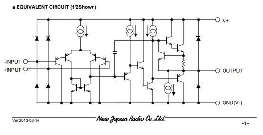
I've created a custom board with a SIM800C. I'll show the schematic above: enter image description here
enter image description here

My VIN is aproximately 4.8V. MY "4V" line is constant. I'm able to comunicate with the module, but sometime's doesn't work and I always receive a "+CREG 0,0". Using the osciloscope to see the TX line from the module, I saw that the maximum voltage is 1V (wich doesnt seen correct). When I send "AT" I see some activity, but I think I'm not able to receive it becauve of the level... Can someone help me?

enter image description here

The first signal worked fine (I received a "OK"), but the second one I only received weird characters...

UPDATE

I took of my regulator and solder a wire directly to my source (>2A and 4.2V) and this is what I got:
enter image description here

enter image description here

  • What is the peak current needed by the SIM800C? The linear regulator probably cannot deliver this. Can you connect a low ESR 470 uF parallel to C37? – Jens Jun 23 '23 at 17:59
  • I saw that it needs 2A... I'm going to try this tomorrow and I'll come back with the feedback. – ANTONIO EMILIO PEREIRA Jun 24 '23 at 03:00
  • I didn't find a Capacitor, but I took of my regulator and solder a wire directly to my power source (with >2A and 4.2V) and still didnt work... I uploaded the new return I got on the main question. – ANTONIO EMILIO PEREIRA Jun 24 '23 at 20:00
  • GSM module operates on 1.8V domain for all the peripherals, including tx and rx, you need a level shifter to translate your MCU voltage to 1.8v for all the interface with the module. BTW, VDD_EXT output a 1.8v for powering the one side of the level shifter. I don't understand why you have 100k resistor on the line? and what is exactly the G_VDD? – hcheung Jun 25 '23 at 12:37
  • Actually I used a schematic that one friend recomended me...So I should probably take off this 100k resistor, right? – ANTONIO EMILIO PEREIRA Jun 25 '23 at 16:29

0 Answers0