4

I am testing a flyback converter with secondary side regulation, by means of a 431 in conjunction with an optocoupler with nominal CTR of 50-100%. A snippet of the regulator part is below.

I have used the 431 before to regulate non-isolated supplies (Sepic, Cuk) using the same 431 and modulator without issues, i.e. I didn't use the optocoupler in the feedback of those supplies.

schematic

simulate this circuit – Schematic created using CircuitLab

The full schematic is here:

enter image description here

The issue

According to my spice sims (using the 431 model from Diode's website), the regulator should be stable as shown in the schematic. The switching frequency is approx. 1.3 MHz. It is stable with no Iload at all, or with various load currents, up to 100 mA in this test. It becomes unstable if the compensation capacitor C1 is smaller than ~100 pF, or if the 5V capacitor is smaller than approximately 1 uF.

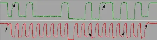
However, the actual converter is ringing heavily, overshooting and undershooting the regulation at irregular intervals. All the voltage waveforms on the primary side modulator look completely as expected, with the only exception being the feedback node that is pulled on by the opto. This feedback seems to over-react. Therefore, I suspect an issue with the regulator compensation. This feedback node on the primary side has an impedance of 33 kΩ || 100 pF.

Adding some load current of around 50 mA made the regulation a bit better, but it was still changing between essentially maximum duty cycle (50%) and fully off phases.

I then added a 120 µF electrolytic cap on the output to provide a large high frequency load. This fixed stability at higher frequencies. But now the regulator is ringing at a pretty constant frequency of about 2 kHz. Where "ringing" means toggling between off and a few pulses of high-duty operation.

Is there some general suspicion to be made about the compensation scheme? Can the frequency of the ringing (2 kHz) be a trace to some part of the regulation loop that I could fix? Does the opto perhaps restrict regulation bandwidth considerably over the non-isolated supplies I built succesfully using the same modulator and regulation? The opto datasheet lists 3-4 µs as toggle time, so it should be plenty fast for the time constant of voltage sense node (33 µs).

tobalt
  • 18,646
  • 16
  • 73
  • What is the used converter frequency? Is it possible, that the coupler itself is too slow? – Jens Jun 23 '23 at 16:52
  • @Jens Do you mean the switching frequency mentioned in the question? That would be 1.3 MHz. I suspect the opto, too, as it is the part I have no prior experience with. But according to the datasheet, I would infer that it is fast enough actually. – tobalt Jun 23 '23 at 17:00
  • The respose times of the coupler are defined for a 100 ohm load, but here you have 33 kohm. Your switching frequency is 10 times faster than all the circuits I have seen using this 431 and coupler circuit. Interesting - which SMPS driving circuit do you use? – Jens Jun 23 '23 at 17:10
  • @Jens hmm I see. Do you think the opto could be as slow as 2 kHz given the high impedance in the feedback node? Wanna formulate an answer based on that? Drive is comparator straight into a small MOSFET. Vin is 48V (no offline converter), so the FET is small. It turns on in about 10 ns without additional driver. – tobalt Jun 23 '23 at 17:28
  • What load current is the phototransistor running at? What voltage gain? To make it concrete, what is the rest of the circuit (controller, output filter)? – Tim Williams Jun 24 '23 at 03:15
  • @TimWilliams I have added a shot of the full schematic. Note that the 10 uF cap needs severe derating at 5 V (approx. half capacitance). – tobalt Jun 27 '23 at 06:44
  • So it's a hysteretic voltage mode control? Yeah, chaos is pretty normal there. Well-behaved control schemes can be cycle-averaged around, and a linear control law derived, but I suspect that is not the case here, so you just get whatever. – Tim Williams Jun 27 '23 at 07:20
  • @TimWilliams The oscillator is hysteretic, the control loop is not. It adjusts the PWM smoothly between 0 and 50% duty cycle, depending on load requirement. I believe, it behaves like a PI regulator. – tobalt Jun 27 '23 at 07:50
  • @tobalt, please check this [document](http://powersimtof.com/Downloads/PPTs/The%20TL431%20in%20Switching%20Power%20Supplies.pdf) on the TL431 I published some years ago, you should find the data you need. – Verbal Kint Jul 24 '23 at 11:19

1 Answers1

4

I think the coupler response time is too slow for the desired feedback loop.

The datasheet specifies a maximum of 18 µs rise and fall time with 100 ohm load and 2 mA collector current. We are far from this here with 33 kohm load.

Another problem is, that the response is not symmetrical. The coupler output capacitance can be discharged quickly if the LED is driven, but only slowly discharged via the load resistor. This will produce overshoot.

A first attempt is to lower the load resistor to enable 2 mA current as midpoint for the regulation.

If this is still too slow, it is possible to use only the BE diode of a coupler as photo diode. This needs another coupler with access to the base. In this case 33 kohm load may be appropriate.

Jens
  • 5,598
  • 2
  • 7
  • 28
  • Indeed it looks likely that the opto is already limiting at this low frequency. I was always wondering why people used so high opto currents of several mA. Lower impedance on the opto output and more opto current would also remove the need for R1.. Will test in the next days to check. – tobalt Jun 23 '23 at 19:00
  • I did two tests: 1) increased compensation cap to 10 nF which should put bandwidth safely below the opto speed limit -> still ringing, but at a faster frequency now ~8kHz with less amplitude. 2) I tested the opto model in spice, and it very well accounts for the slow rise/fall times when in a high impedance load. Regardless, the spice sim of the flyback regulator is very stable with no ringing. At the moment I am trying to reproduce the real behavior in spice for more hints. I am suspecting VIN stability issues. – tobalt Jun 27 '23 at 06:36