0

I have a requirement to design a bare bone, inexpensive 90 v 700 W reversable DC motor drive. I have attached the schematic showing the drive components. The prototype works well at speed, but occasionally blows R16 and or C15 at first power up. Ratings seems to be comfortably in range. Note that the diode D1 clamps reverse EMF and wind-down voltage when reversing the motor direction.

Can anyone see an issue here, or a way to improve the reliability of the design? Thanks so much for your input.
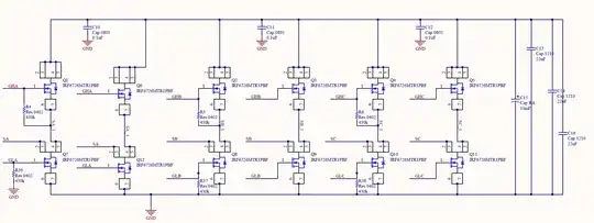
Drive Circuit

JerryR
  • 1
  • 1
  • What component ratings? What control scheme? If the ratings are sufficient, the issue seems trivially avoided by current-mode control or protection. – Tim Williams Jun 22 '23 at 13:28
  • 1
    What's the motor winding resistance, to get an idea of stall current? 700W tells us current under load, but not start/stall current. – Simon Fitch Jun 22 '23 at 13:48
  • Maybe the inductance of R16 is applying reverse voltage to the cap? Or the inductance is causing a voltage spike during power up. Can you soft start the motor by applying some PWM before you turn it fully on? – Drew Jun 22 '23 at 13:57
  • I also agree with Simon, you need to make sure the driver can handle the fast overload that will occur during power up. Now that I think about it, C15 is probably blowing up *after* R16. – Drew Jun 22 '23 at 13:59
  • On power up: Is the high voltage available before the gate driver can pull down the gate? The reverse transfer capacitance (120 pF) can win against 10 kohm (R14). – Jens Jun 22 '23 at 16:43

0 Answers0