0

In my project I have an optocoupler Rail 32 units like the proto below . I want to link it to my MCU with 2 mcp23017 digital Input . Do I need to put a Schmitt Trigger before the mcp23017 to have a perfect electronic PCB signal as i have a common 5 dc volt and how to size the 5 volt supply for the 32 optocouplers .And want to optional count the pulses input to make some scenario like 1 pulse ON/OFF nb 2 pulse for an other action..
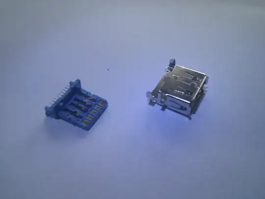
enter image description here Note 24dc trigger input on the optocoupler link to a switch

5dc volt output to digital input mcp23017
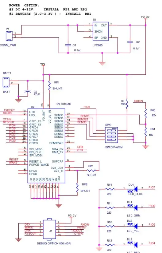
Here is the new circuitenter image description here

  • Fix your schematic first. You marked Q5 as PNP3906 but you used NPN symbol. Even if I replace it with a proper PNP (assuming the emitter is connected to R5 and collector is connected to R4) I can't see whether the circuit is going to work. Fix the schematic then we'll answer your questions. – Rohat Kılıç Jun 21 '23 at 13:35
  • Sure i have made a mistake value on R5 and R3 R4 is good I am hasking if a get a value signal to put a none inverting schmitt trigger just after point 1 before enter to the mcp23017 input pin hope it's more clear – Khales Naim Jun 21 '23 at 16:25
  • The I/O extender IC has an internal Schmitt Trigger, all you need is to connect the coupler output between +5 V and the IC input and a resistor (R4) to GND. Remove R3, R5 and the PNP. Use higher values for R1 and R2 (1 kohm). – Jens Jun 21 '23 at 17:41
  • Thank you very much Jens for your reply I have made a quick researche about mcp23017 I have seen no where about Schmitt trigger filter do you have a link . I have some question about i2c line comming from mcu do i have to put 4.7k for each mcp23017 I have 4 units on the pcb or just a pair on output pin of SDA SCl of the mcu. How to size the Current of 5 dc supply i 32 imput – Khales Naim Jun 22 '23 at 08:42

0 Answers0