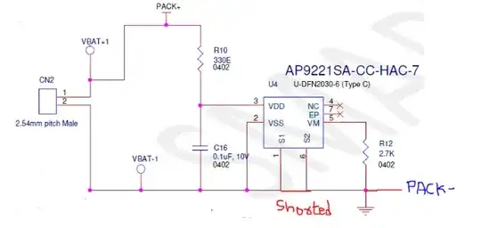
I am using AP9221SA-CC-HAC-7 PCM IC with 1-cell Li-ion battery (4.2V). I have battery charger (RT9471) after PCM IC and load connected after battery charger. The PACK+ and PACK- signals go the the battery charger supply pins. Load is never disconnected in this system. The part of schematic is as shown in the image attached.
Now, my battery is discharged to 2.957V. According to the datasheet of AP9221SA-CC-HAC-7, it is between Over discharge upper threshold (2.97V) and lower threshold range (2.85V) so it should be in Over-discharge state. When I measured voltage across PAC+ and PACK-, I observed a voltage of 0.07V.The system was not functioning as input supply to battery voltage is low in this case (0.07V).
I inserted a USB Type-C Charger which supplies the charging voltage to the VBUS pin of Battery charger. Still the battery is not charging (when voltage measured across CN2). At this time, when I measured the voltage across PACK+ and PACK- the voltage was 0.6V.The voltage at REGN pin of battery charger was 5.0V I left the Charger connected to the system for about an hour and then measured voltage across PACK+ and PACK-, it remained at 2.957V.
I also bypassed PCM by connecting VSS and PACK-. At this time battery started to charge. I again connected a battery of 2.957V and inserted charger (USB Type-C). Now the battery charged (Voltage increased).
Now my question is:
- Why is battery not charging when PMIC is present and Charger is inserted?
- Why the voltage at PACK+ and PACK- o.6V when charger is inserted?
Please help me on this one. Also I chose AP9221SA-CC-HAC-7 as there were internal FETs present and my board has space constraint issue.
AP9221SA-CC-HAC-7 Datasheet: https://www.mouser.in/datasheet/2/115/DIOD_S_A0012884324_1-2543822.pdf
RT9471D Datasheet: https://www.richtek.com/assets/product_file/RT9471=RT9471D/DS9471D-02.pdf


