0

I am trying to make a UPS, which will need to pass safety regulations. I need to detect:

  • When the mains AC voltage is present
  • When the mains AC voltage is under/over voltage

I thought of using a capacitive power supply because it has high charge/discharge speed, unlike an SMPS which takes a long time to charge/discharge. The detection time I need for mains failing is less than 5 ms. The detect signal would drive an MCU input GPIO pin. That line would have a TVS and other over-voltage protection for the pin.

I know capacitive power supplies are inefficient, and can be lethal if they misbehave, but is there any other fast switching alternative?

This is how it looks in the picture. The 120 Ω resistor is used to pull the voltage to approximately 3..4 V so the MCU can read it. Would such a circuit work properly?

enter image description here

TonyM
  • 21,742
  • 4
  • 39
  • 62
  • You don't need a power supply, you need a measurement circuit. – Justme Jun 15 '23 at 08:40
  • that's correct but how can I measure 220VAC mains as a DC signal? – Hazardous Voltage Jun 15 '23 at 09:00
  • 1
    Good heavens! Are you planning on implementing a power supply in order to _measure_ voltage? – winny Jun 15 '23 at 10:35
  • 3
    240VAC has a peak of 340V. C1 is massively under-rated – Mukira Jun 15 '23 at 10:43
  • 2
    `it needs to pass the safety regulations` which regulations and which class? Does your safety requirements say anything about isolation from mains? Is GND lane user-accesible? – Rohat Kılıç Jun 15 '23 at 10:59
  • 1
    calm down guys, firstly, I already stated in my question that I need a circuit which could help to measure the 220V mains although I was asking for a standardized idea, so if you could better to give an idea. Secondly the capacitor is 275VAC rated(yellow X2 capacitors) so it would work just fine. Third, yes it would be Isolated for most part but the capacitor part is not so for that I am asking if something instead of SMPS(because it is relatively slow in charging/discharging) so I can make fully isolated. the device would be enclosed in black dyed(isolated dye) aluminum body. – Hazardous Voltage Jun 15 '23 at 11:24
  • _"Isolated for most part"_ You either are isolated or you aren't. Which is it? Why not a diode bridge + voltage divider if you're not isolated or tiny transformer+rectifier if you are isolated? Optocoupler could be an option but may need individual trimming or perhaps proportional PWM generation if you want accuracy. – winny Jun 15 '23 at 14:03
  • 2
    One cycle of 50 Hz power is 20 ms, so detecting a power failure in under 5 ms is not possible. – Peter Bennett Jun 15 '23 at 15:32
  • If so then how do normal UPSs works?I think it is possible when the power goes down it should be detected, am I right?? – Hazardous Voltage Jun 15 '23 at 19:17
  • @winny I mean for most part that only the capacitive power supply is not isolated but how can I control it by PWM when the mains is 220V? – Hazardous Voltage Jun 15 '23 at 20:30
  • Again, connecting a non-isolated supply to a circuit otherwise isolated would make the entire circuit non-isolated. It's like a woman being pregnant. You can't just be a little bit pregnant, you either are or you're not. There are several way to implement it. To get rid of CTR and temperature variations of the optocoupler, I would measure and encode the AC voltage as a PWM duty cycle and send that via the optocoupler to the secondary. – winny Jun 16 '23 at 07:06
  • 1
    From the question and the comment chain, I think this is an X-Y problem. Things like wanting to control this through PWM and so on mean that you're asking about the details without explaining the overall principles of the whole system and the latter may be misled or erroneous. Voting to close for that reason. Extra detail should be edited into the question, not posted as comments. – TonyM Jun 16 '23 at 08:52
  • @winny so how would you measure it and encode it, you mean you need to step it down right? Or can you just get it from the 220vac mains? – Hazardous Voltage Jun 16 '23 at 11:22
  • @TonyM can you please inform me what details are missing that you need? – Hazardous Voltage Jun 16 '23 at 11:23
  • 1
    I already have, in the comment you read. It's not adding what 'I need', it's writing a clear and detailed question for everyone. That might bring in some answers. You can see the traffic's stopped here - that's why. – TonyM Jun 16 '23 at 11:56

2 Answers2

2

What you want here isn't a power supply, but a measurement system.

If you only want to know whether there's AC present or not, that's trivially easy to do with an optocoupler or solid-state relay:
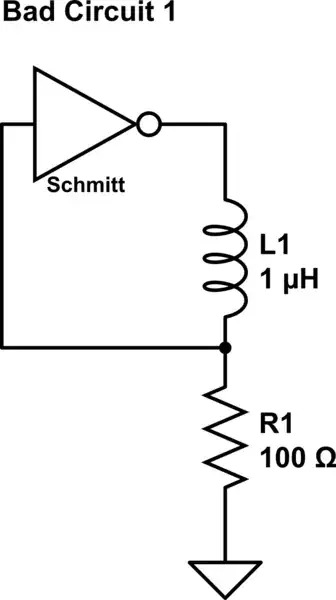
schematic

simulate this circuit – Schematic created using CircuitLab


If you want to compare the line voltage to a fixed value, that's also fairly simple; rectify it, divide it down, and use a comparator to compare the peaks to a voltage reference. Then pass the output of that comparator through an optocoupler to your output side.


If you want to measure the voltage with a little bit of precision, you can use a linear optocoupler like the aforementioned H11AA1, but you'll have to measure the current transfer ratio and calibrate that out in software.

The current transfer ratio, or CTR, is defined as \$\frac{I_{input}}{I_{output}}\$; if you give the optocoupler an input current of say 10 mA, and if the optocoupler has a CTR of say 50%, then the output current, provided there's enough voltage available that the output transistor isn't saturated, will be 5 mA.

The CTR varies quite a lot from device to device (I've never seen an optocoupler with tighter than a 1-to-2 spread, and they're more often on the order of 1-to-10), and it varies with temperature as well. In addition, the CTR changes (usually decreasing) as the device ages, so you'll need to compensate for that too, if you don't want old devices to constantly trip the undervoltage alarm.

Here's the most basic circuit for doing that. It's not too different from the circuit I show above, but this one is non-inverting:
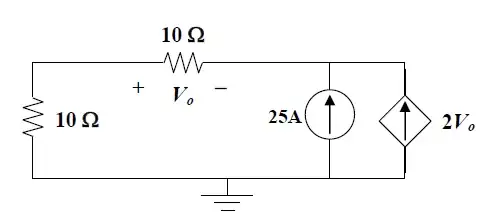
schematic

simulate this circuit

R1 functions to convert the AC voltage to a current (we can assume the LED forward voltage is negligible in comparison to common mains voltages; if you're measuring low voltage AC you will want to compensate for it), then the optocoupler transfers that current over the isolation barrier and applies its CTR to it, then R2 converts that current back into a voltage, which can be measured with an ADC and then used to back-calculate what the AC input was:

$$\begin{align} V_{ADC} &= I_{output}·R2\\ V_{ADC} &= I_{input}·CTR·R2\\ V_{ADC} &= \frac{V_{AC} - V_f}{R1}·CTR·R2\\ \frac{R1}{R2}·V_{ADC} &= (V_{AC} - V_f)·CTR\\ \frac{1}{CTR}·\frac{R1}{R2}·V_{ADC} &= V_{AC} - V_f\\ \frac{1}{CTR}·\frac{R1}{R2}·V_{ADC} + V_f &= V_{AC}. \end{align}$$

Note that, for the H11AA1 shown here, positive and negative AC voltages will give the same response; you can't determine the AC polarity with this circuit.

You can trim the CTR in the analog domain by adding a resistor from base to emitter of the optocoupler (which lowers the effective CTR depending on the resistance--lower resistance means lower CTR), or in the digital domain by adjusting the constants in that calculation.

This is not an accurate measurement. The main source of error is the CTR, which (as previously mentioned) varies significantly from device to device, changes with temperature, and slowly degrades as the device ages. If your device is frequently turned on and off, and if it's safe to assume that the measured voltage will be within the expected range when the device is turned on, you can just automatically calibrate every time it's powered up and, instead of looking for specific numbers, look for specific deviations from the number it saw on power-up.

Obviously, all measurements here will need to take into consideration the fact that AC is AC. You don't want your device deciding it's lost AC power just because you measured the voltage a few milliseconds before the AC peak. Either synchronize your measurements to happen at the same time every half-cycle, or take measurements frequently enough that you can reconstruct the whole sine wave and look at that. It's easy to synchronize measurements here, because you can use the optocoupler's output itself as a timing reference; it will go low for a handful of milliseconds at each zero crossing.


If you want to measure it accurately, you'll need to set up a measurement circuit on the high-voltage side, feed that into an ADC, and connect the output of the ADC to your MCU through a digital isolator of some kind. This is the most straightforward way, though it may be a bit involved.

Another option would be to use a current transformer, if you happen to be more interested in the AC current than its voltage (or your application allows the two to be considered interchangeable, like if you have a known resistive load on the AC). This would avoid the need for a high-side power supply, ADC, and digital isolator.
Hearth
  • 27,177
  • 3
  • 51
  • 115
  • 1
    I tried the optocoupler and it works fine, but the problem I can't measure if there is an over voltage or under voltage so how could I get it with an optocoupler? – Hazardous Voltage Jun 15 '23 at 19:35
  • 2
    @HazardousVoltage I described solutions for that as well; what do you not follow? Do you want to compare to one or two fixed voltages, or do you want to get an accurate measurement? – Hearth Jun 15 '23 at 22:55
  • I get your point although I would be more interested in an approximate measurement using the optocoupler, but I don't get how it would measure when it is under/over voltage, what would be the mechanism? – Hazardous Voltage Jun 16 '23 at 11:20
  • Comparator and reference. Perhaps just use two optocouplers and transfer each signal separately. – winny Jun 16 '23 at 16:03
  • @HazardousVoltage I've elaborated on how to do that. – Hearth Jun 16 '23 at 16:22
  • @winny yes mate I would do it like this using 2 optos they wold be separated for over and under voltage I guess it would be the easiest – Hazardous Voltage Jun 16 '23 at 17:19
  • @Hearth I will be reading and try to understand your idea and replace the CTR with a shunt resistor so it would be more reliable and easier to calculate – Hazardous Voltage Jun 16 '23 at 17:43
  • @HazardousVoltage What do you mean "replace the CTR with a shunt resistor"? You can't replace the CTR, it's a performance metric. That would be like saying "replace the distance with a banana"--it makes no sense. – Hearth Jun 16 '23 at 17:44
  • @Hearth my bad I did misunderstand it as Current Transformer not Current Transfer Ratio, I meant to say that I would be using a shunt resistor to sense the AC signal because in the mean time I have no Optocoupler I can use it – Hazardous Voltage Jun 16 '23 at 18:15
  • 1
    @HazardousVoltage You should *always* use an optocoupler or some other form of isolation when sensing mains voltage. – Hearth Jun 16 '23 at 19:26
  • _”replace the CTR”_ This makes no sense. Sorry to be the one to tell you, but a UPS design requires a higher skill level. Your lack of understanding what an isolated circuit is and why you need it tells me you need to work on simpler projects before you do anything mains connected. – winny Jun 17 '23 at 06:28
-1

You could do it with an optocoupler replacing your bridge and add a pull up resistor to the output of the optocoupler then to the MCU. There are many approved for this application. Some will also be bidirectional on the input so you can get the positive and negative haves of the signal. This would be layout critical. I have also done it by using a small transformer in front of the optocoupler, that makes isolation much easier.

The mains voltage can be measured from the internal power supply. If it is a custom transformer you can add a winding to do both functions.

Gil
  • 4,951
  • 2
  • 12
  • 14
  • 1
    I would be delighted if you could share the circuit with me, I thought of making it with an optocoupler but how to measure over/under voltage? – Hazardous Voltage Jun 15 '23 at 11:16