I've see a number of terms that make reference to the word "bias". I've read the wikipedia article but I'm after are more practical answer.
Some examples of what a forward or reverse biased device is would also be well received.
I've see a number of terms that make reference to the word "bias". I've read the wikipedia article but I'm after are more practical answer.
Some examples of what a forward or reverse biased device is would also be well received.
Bias is another word for the operating point -- a dc voltage or current about which the instantaneous value might vary.
For example, you can say you applied a "6 V peak-peak AC signal biased at +1 V". In this case the range of the signal would be from -2 to +4 V. You can see the relationship with the everyday meaning of bias, "a tendency or inclination" (dictionary.com) in this case with the meaning that although the voltage varies, it tends to be near the operating point.
As the other answers point out, the term is often used with relation to diodes and other nonlinear components.
Bias is essentially offset. If you have a biased opinion, you are displaced from a neutral position.
In floating-point number representations, like IEEE 754, the exponent field is said to be biased. A zero exponent is represented by some middle value like 10000000000, rather than using two's complement, which would create a situation in which there are two sign bits. This allows floating-point numbers, as a whole, to be compared for inequality using purely integer operations. But we digress: the point here is that an offset is called bias, not only in electronics.
You could identify a systematic offset in some statistical data. That is also a bias.
If an AC signal rides on a DC signal, we can simply say that it has a DC bias of so many volts, though not always.
In electronics, a bias is usually deliberate, as in an "offset required for proper operation"; it does not have a negative meaning like in "biased sampling" or "biased opinion". An unwanted offset is just an "offset". If the output of a quiescent amplifier is supposed to be ideally at 0V, but it measures at 25 mV, then we usually say that the amplifier has a "25 mV DC offset", rather than a "25 mV bias".
There are situations in which a signal is added for proper operation, but it is not a simple fixed offset; yet, it is still called a bias. When a signal such as audio is recorded to magnetic tape, this is done with the addition of tape bias: a high frequency AC signal. This bias signal improves the linearity of the magnetization, reducing distortion from the hysteresis of the tape's magnetic particles. Different tape materials work better with different amounts of this bias.
To give a slightly different answer on top of what everyone else has already beaten me to: You forward bias a diode by applying a DC voltage greater than or equal to its forward drop voltage. A BJT can be looked at as two diodes, but it's more complicated than that.
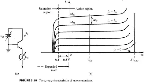
In amplifier theory, you specifically design amplifiers to be biased so that they have the largest 'dynamic range'. This refers to the peak amplitude of the waves that you can put in and get out of the amplifier. A good amplifier (which can be a single BJT and some resistors, look up Common Emitter/Collector/Base Amplfiers, etc) will have a very large dynamic range. You can get the largest dynamic range out of an amplifier by biasing it to be in the exact middle of the saturation region which is this flat zone along the IV curve of the BJT:
Our output wave comes out with a vertical (DC) offset equivalent to our biasing -- it 'rides' on top of the DC. This gives us our dynamic range. When we increase our amplitude of the input wave, the output wave will grow until it either hits the top (your voltage rail) or the bottom (the linear region), whichever is closer. Biasing in the middle gives us the most space on either side.
Why do we want to be in the middle? Again, because of that nice constant relationship between input voltage and current. If we were to fall into the linear/active region then the bottom part of your wave gets distorted.
So back to the diode: If we were to bias it to only 0.7V (a common forward drop voltage), then we couldn't ride any AC signal on top of it, since the bottom lobes would cause that voltage to dip below 0.7V and turn the diode off. So if we bias a 0.7V diode instead to 1V, we could then ride a .3V AC signal through it without worrying that it will turn off.
Forward or reverse biased usually applies to diodes. A forward biased diode has a higher voltage at its anode than its cathode. If this is higher than the (small) threshold it conducts in that direction. A reverse biased diode has a higher voltage at its cathode than its anode, and will not conduct (unless you exceed the breakdown voltage and destroy it).
Biasing in an audio context usually refers to an arrangement to keep the middle of a signal in the centre range of an amplifier. This gives the best use of the output range of the amplifier.
A diode can be forward biased or reverse biased depending on what polarity the voltage is across it. In forward bias, a diode conducts easily and offers only a small conduction loss to the current it passes. When reverse biased a diode hardly conducts at all - some diodes might conduct a few micro-amps and some diodes significantly less however, as more reverse voltage is applied, you will bring about a sudden change in current - the diode is said to "break-down"
A bipolar-junction-transistor works by applying a forward bias to the base-emitter junction (this junction is essentially a diode) - the amount of forward bias you apply sets the current through the collector. If the base-emitter of a BJT is reverse biased it isn't able to be used as an amplifier unless the signal (also applied to the base-emitter) helps forward bias the transistor - this is a useful way of driving in the BJT in what are known as class C amplifiers but, most BJT amplifiers operate in class A where the base-emitter is always forward biased even when the input signal is at its most extreme limits.