0

Previously I asked for help with a power supply for titanium anodizing and my requirements were too vague. After doing some testing I believe I have found a schematic which I was able to use and change for my requirements.

I would like to improve upon the circuit if possible.

Voltage dictates color while anodizing. Currently when I get to around 40-50V it seems like I need more voltage than expected to get the color. I'm not sure if I’m explaining this part correctly.

There is no transformer and the bridge rectifier is getting 120VAC 60Hz mains.

  • C1 is 330 uF polarized
  • T1 is IRF634
  • T2 is 2SC3855
  • R1 is 180 kΩ
  • R2 is 8 Ω
  • R3 is 500 kΩ
  • D2 is an SA5.0A

After R3 there is:

  • A 68 uF polarized cap
  • A 224 bi polar cap

A 10 kΩ resistor with blue LED in series, and a 5.1 kΩ resistor with two yellow LEDs. Both are to simulate a load when there isn’t one connected.

Please note the resistance of the titanium changes while it anodizes. As voltage increases, the layer of anodization becomes thicker and the resistance of the object increases.

source follower voltage regulator

Credits for the design to Swagatam .

The original design and article can be found here.

JRE
  • 67,678
  • 8
  • 104
  • 179
Infernoman
  • 43
  • 6
  • 1
    In what way would you like it improved? What is letting it down at the moment? We can't answer these things; you need to fill-in the details of what you want it to become from what it currently is. – Andy aka Jun 06 '23 at 11:16
  • @Andyaka I don’t have a background or schooling for electrical engineering so honestly I’m looking for the basics. I would like to improve the regulation of the circuit, add a pull down resistor on the gate and any other recommendations similar to these. I’m also using a unidirectional tvs diode instead of a Zener diode which was already a stretch for me – Infernoman Jun 06 '23 at 11:31
  • 1
    OK, ditch the MOSFET and try a suitably rated bipolar NPN transistor; it will have a better regulation and, if that isn't good enough you can use an op-amp to improve the basic regulation. Then, if it all gets too hot, use a buck converter. – Andy aka Jun 06 '23 at 11:47
  • 1
    I have a 2sc5200 rated for 250v, but it has a pretty low hfe. Will this work okay? And should I remove the sa5.0a diode from the base/emitter? – Infernoman Jun 06 '23 at 11:56
  • If that's all you have you should try it however, the former gate biasing arrangement needs to be redesigned for an NPN transistor and, this might be a little tricky because the resistors will need to be considerably lower in value and potentially pose heat dissipation problems in R3. The alternative is to use a variac voltage controller on the AC side. – Andy aka Jun 06 '23 at 12:22
  • Okay @Andyaka let’s see if I have this right… with an hfe of 75. And output current of 87.5ma. R3 should only be passing ~1.16ma. So if R1 was 10k, there would be a drop of 16v across it. So like you said I would also need a smaller potentiometer probably closer to 10k, but possibly even smaller. And it would need to be a 5w potentiometer to handle the power dissipation. – Infernoman Jun 06 '23 at 12:53
  • Yes, it gets a tad messy but... doable. – Andy aka Jun 06 '23 at 12:56
  • @Infernoman - Hi, Please remember the [site rule](/help/referencing) which requires that when a post includes content (e.g. text, image, photo etc.) copied or adapted from elsewhere, that original content must be correctly referenced. The *correct* source webpage or PDF etc. should be linked as a minimum (references for books / articles should include title, author(s), publisher, edition, page numbers etc.). Please can you edit your question to include the required source link for the original image? Thanks. (You can remind yourself of the main site rules by reading the [tour] & [help].) – SamGibson Jun 06 '23 at 14:37
  • 1
    As a matter of improved safety (not a matter of performance), I'd insert a 3W 150 ohm resistor between bridge diodes and C1. As is, the turn-on surge current is brutal. – glen_geek Jun 06 '23 at 14:43
  • 1
    These kind of linear MOSFET circuits sometimes produce high frequency oscillations around the DC operating point. You can slow down the FET with an additional capacitor between gate and source. 10 nF is a good starting point I guess. – Jens Jun 06 '23 at 18:33
  • @glen_geek I had an 80 ohm 15w available and added that. Thank you. I’ve also added a 10nf capacitor between the gate and source terminals. And a 10uf between the gate and ground. Is there any benefit having a pull down resistor from gate to source? Or a higher voltage Zener diode instead of a unidirectional tvs? – Infernoman Jun 07 '23 at 03:41
  • @SamGibson I will update this as soon as I get to the PC, currently on mobile. Thanks for the reminder and I’ll make sure to look over the rules again. It was a late night frustrated post lol. – Infernoman Jun 07 '23 at 03:42
  • _"A 224 bi polar cap"_ Would this be 220 nF by any chance? – winny Jun 07 '23 at 14:35
  • Diode D2 is backwards. – AnalogKid Jun 07 '23 at 17:06
  • No, I think it's OK as is, to keep Vgs below 12V. – PStechPaul Jun 07 '23 at 21:23
  • Yes the 224 is 220nF. And PStechPaul is correct. The diode is there to keep vgs below 12v. – Infernoman Jun 08 '23 at 14:24

2 Answers2

1

I think your problem lies in the red marked parts of the circuit:

enter image description here

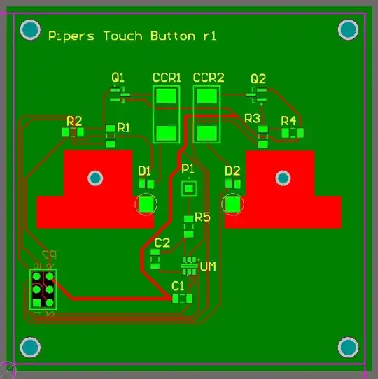
That's a current limiter. It limits the current by reducing the voltage.

R2 and T2 limit the current. When the current rises, T2 will start to pull the gate voltage towards the source voltage. That has the same effect as turning down the voltage with R3.

In the original circuit, T2 and R3 were selected for a claimed limit of 100mA. You say you are using a different transistor for T2 and 8 ohms for R2 instead of the original 3.3 ohms - I expect your circuit is limiting the current to a good bit less than 100mA.

I've read through your descriptions, and it seems that you aren't measuring the voltage at all. If you meausure the voltage while the system is running, then I expect you will find that the voltage drops over time. It may not even start out at the set voltage if your anodizing bath draws more current from the start than the limiter allows.

You probably need to remove R2 and T2 - that will allow the needed current to flow for the voltage you set with R3.

Since the required current varies with the surface area, you will find that larger objects take more current. At some point, a large object may draw more current than either transistor T1 or the rectifier bridge are rated for - they may burn or pop. If those parts are rated high enough, you might blow a fuse (or trip a circuit breaker) in your house.

Have a look here for an overview of what goes into anodizing.

You really need the following things to make your anodizing power supply:

  1. Isolation so you don't kill yourself or someone else (a 1:1 isolation transformer would do the job.)
  2. Voltage control to set the color.
  3. Current control to manage how fast the anodizing builds up. As I understand it, too much current makes the anodized layer grow so fast that you may "overshoot" the color.
  4. A voltmeter to check the voltage while anodizing.
  5. An ammeter to check the current while anodizing.
  6. A fuse or circuit breaker to shut things off if there's a short circuit in the anodizing bath.

It would probably be safer to purchase a complete lab power supply rated for up to 100V and a couple of amperes. Even the cheapest power supply on Amazon will be safer than twiddling with voltages and currents that can kill you.


Be very careful working with this circuit. As you have described it, you are connecting this contraption straight to the mains - no transformer between the mains an the rectifier. Any part of that circuit can be at a voltage high enough to kill you.

  1. Make sure you have a working GFCI for the outlet you are using.
  2. Never touch any part of the system while it is operating.
  3. Only change connections when the system is unplugged (and double check to be sure that it is disconnected.)
  4. Only change connections after allowing C1 to discharge. R3 will do that, but you will want to wait a couple of minutes before touching anything.

I've read that Best Technology page again and some other stuff and I think this works differently than the way they (and the OP) express it.

  • The color is determined by how thick the anodized layer is.
  • The thicker the layer the more resistance it has.
  • A thick layer takes a higher voltage to add more anodizing.
  • Anodizing quickly requires more current.

The voltage itself doesn't cause the color. The voltage is only an indicator of the anodized thickness.

You've got two ways to do this:

  1. Anodize fast (high current) with a voltage limit to automatically slow (or stop) the anodizing when the layer is thick enough for the desired color.
  2. Anodize slowly (low current) then watch the progress and stop when you get the color you want.

If the current output is really low, then you might simply need a lot of patience for the anodizing to reach the needed thickness.

Your power supply could, for example, provide a maximum of 100VDC but at 10mA. It would slowly anodize the object, with the voltage slowly rising to maintain the 10mA. It might take a very long time to reach the thickest coating, but you could stop at any time when you see the color you want.

In other words, you want a either constant current power supply with a voltage limit for fast anodizing or a constant current power supply with low current and just watch the color.

JRE
  • 67,678
  • 8
  • 104
  • 179
  • Thanks for your in depth explanation. Only thing I have to add is that when you use too much current, you get pitting in the titanium. Learned that the hard way. Eventually I’d like to swap R2 for a high power wirewound pot once I have an anmeter. I decided to go on the safer side with 8 ohms since the current output was dependant on the hfe of the transistor chosen and didn’t know how to calculate that. I do have a 5 amp circuit breaker before the 80ohm resistor I added yesterday to slow the inrush current. And it is connected to a GFCI outlet. Just missing the isolation transformer. – Infernoman Jun 08 '23 at 14:35
  • I would also like to swap R3 for a 10 turn 100k pot and change the mosfet to an irf260n to increase the power handling, but I haven’t had the need for it yet. Most pieces I’ll be anodizing are relatively small. The biggest I’ve done so far are knife scales. Is there any benefit to changing the TVS for a higher voltage Zener diode? Or adding a gate-source resistor? Speaking of the isolation transformer, should the negative side of the DC supply be floating or grounded? And are there any other recommendations you could make? – Infernoman Jun 08 '23 at 14:43
0

This circuit is intended to produce a current-limited more-or-less constant (within a few voltage) output voltage as set on the pot. If it is doing that, any improvement would have to come elsewhere. In other words, if you set 50V at the initial current, the voltage should not rise very much (maybe to 52V) as the anodized layer thickens and the current drops. It will also vary a bit with mains voltage since it is unregulated. And, as you’ve probably been warned, the lack of isolation is dangerous.

If this behavior is not doing what you want, then perhaps there is some other issue with the materials, preparation, or the voltage setting actually needs to be higher.

An “improved” circuit from the point of view of an engineer looking at the original design would hold the voltage even more constant with output current (and mains voltage). However your text implies that you think you want the opposite.

Spehro Pefhany
  • 376,485
  • 21
  • 320
  • 842
  • Currently when the titanium is added to the solution the voltage drops across the piece being anodized and slowly increases to the set voltage within a few volts. When the voltage stabilizes the piece is finished. And everything seems to be working at lower voltages. But after 40-50v the result/color I’m expecting is much different than what I’m getting and it correlates to a lower voltage. – Infernoman Jun 06 '23 at 11:19
  • What voltage do you actually measure? If the supply is providing (say) 75VDC on your multimeter and you are getting unexpected results then the supply is not likely to blame. – Spehro Pefhany Jun 06 '23 at 11:27
  • The output voltage im measuring is correct, but the results are not. For example at 70-75 volts on my multimeter I’m getting gold in color. Which normally you get around 50v. – Infernoman Jun 06 '23 at 11:31
  • Other than lying to you about the voltage, I'm not sure what the supply design can do to help with that. It sounds more like an issue with the Ti alloy, the electrochemical process itself and/or surface preparation (none of which is an appropriate topic for this site). – Spehro Pefhany Jun 06 '23 at 11:43
  • It’s definitely possible that it’s an issue after the power supply. But I’ve tried multiple pieces of titanium. Different preparation methods, and different electrolytes. All of which led back to the same results which is why I’m looking for methods of improving the circuit. Since I only have a basic grasp on mosfets, are there any recommendations you can make to improve the circuit at all? Pull down resistor, better regulation, different diode, etc? – Infernoman Jun 06 '23 at 11:53
  • 1
    If it's providing the the voltage you want with low enough ripple and stable enough, I don't see that any improvements we could suggest will yield much different results. Splitting R1 into two 240k resistors with a 10uF to ground from the center point would yield less ripple. Cap needs to be rated same as C1. – Spehro Pefhany Jun 06 '23 at 11:57