5

I am investigating using a triac instead of a relay to control 250V 10A devices.

However all the 600V 16A triacs come in TO-220 packages.

According to AS/NZS 3100 and AS/NZS 60335.1 I need at least 2mm creepage isolation between 250v circuits, but that is impossible with TO-220.

How do people build 10A circuits with these triacs?

ljbade
  • 177
  • 8
  • 3
    What standards are you referring to? – Andy aka Apr 24 '13 at 17:26
  • 1
    Your 10A triac requirement is a very close match to the 10A device. I think you want some headroom. In general semiconductors are very fast ... at failing when maximum ratings are exceeded. What kind of load is attached? – jippie Apr 24 '13 at 17:46
  • I am looking at Australian standards, specifically AS/NZS 3100 and AS/NZS 60335.1 (equivalent to the IEC standard). The 60335 standard takes precedence over 3100 though. – ljbade Apr 25 '13 at 10:06
  • My rated load is 10A. So I figured a 10A triac would be enough. Perhaps I should bump this up to 12A or 16A. – ljbade Apr 25 '13 at 10:08

3 Answers3

8

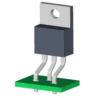
Clearance is about the distance between live and null or about the distance between two isolated circuits. Not so much about the pins on a triac'like device as electrical safety is not an issue in this case. The worst that could happen is that your load stays powered, but fuses will not blow. If you are concerned about the distance between the pins, you can always bend out the middle pin, that is pretty common solution.

It is good practice (thermal expansion'wise) to have a couple small bends anyway in the leads, so the leads won't push the solder pads off the PCB when the pins expand due to the device heating up while being screwed to the heat sink. Bit like this:

enter image description here

Avoid bending pins directly where they come out of the plastic package, as the pins may easily break when doing so.

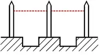
Creepage vs Clearance

  • Creepage is the distance between conductors along insulated surface

enter image description here

  • Clearance is the shortest distance between the conductors

enter image description here

jippie
  • 33,033
  • 16
  • 93
  • 160
  • 2
    Thnx @AnindoGhosh for pointing out the difference between clearance and creepage. – jippie Apr 25 '13 at 05:30
  • That leg staggering trick might work. I also out that I can cut a slot in the PCB between the legs from this - https://www.infineon.com/dgdl/Infineon+-+Application+Note+-+PowerMOSFETs+-+CoolMOS%E2%84%A2+-+Electrical+Safety+and+Isolation+in+high+voltage+Applications.pdf?folderId=db3a304314dca389011528372fbb12ac&fileId=db3a30433d1d0bbe013d20e0cbf017fe – ljbade Apr 25 '13 at 10:10
1

A triac might be controlling a motor and if the triac shorted out, apart from operational safety issues, there are no fire hazards or electric shock hazards. The motor will turn just as if the triac had activated or had burned-out into a blob of conductive metal.

This means, put simply, that is doesn't matter if the physical distance across the triac is less than (say) 2mm - safety will not be jeopardized. Operational safety is another matter of course.

And of course, when controlling a triac from (say) a microcontroller you would choose to use an opto-isolator and the physical distance required across the opto needs to be substantial to significantly reduce the risk of electric shock to the guy programming the micro.
Andy aka
  • 434,556
  • 28
  • 351
  • 777
  • I will also be isolating the gate from the logic via an opto-triac. However the standard still requires minimum creepage for functional isolation where there are only operational issues. – ljbade Apr 25 '13 at 10:15
  • How do you reconcile this with the answer you accepted - the distance at the point where the pins enter the body of the triac are unlikely to be 2mm? Maybe they are? What standard are you referring to anyway? – Andy aka Apr 25 '13 at 10:22
1

Usually it's the logic controlling the gate that gets isolated, not the gate itself. That's why there are optoisolated triac drivers out there on the marketplace.

Primary-to-primary isolation is what's called functional insulation, and doesn't need as much creepage/clearance as primary to user-accessible insulation (reinforced insulation) dictates.

Adam Lawrence
  • 32,921
  • 3
  • 58
  • 110
  • I will also be isolating the gate from the logic via an opto-triac. You are correct that what I was refering to is functional isolation. However the standard still wants 2mm creepage for functional isolation. – ljbade Apr 25 '13 at 10:14
  • I found an older copy of IEC60335-1, and it says that for working voltages between 125 and 250V, you only need 0.4mm for pollution degree 1, and 1.8mm for pollution degree 2, overvoltage category 2 (Table 18). You would need to conformally coat the board to meet PD1. – Adam Lawrence Apr 25 '13 at 13:32
  • Thanks. Hmm that's interesting. I see that too, didn't realise that it is that easy to get to pollution degree 1. The other option I was think of is cutting a slot between the pins in the PCB to convert creepage to clearance distance only. – ljbade Apr 25 '13 at 18:17
  • A slot is a perfectly acceptable alternate to conformal coating for applications like this. – Adam Lawrence Apr 25 '13 at 18:50