There is an answer to this question, but it is not the answer you are expecting:
The questions you must first ask are,
What are some potential outcomes, and how can I measure them?
What is my hypothesis?
What will invalidate my hypothesis?
First, I'm not aware of any dependent effects at all. I have a background in EE, physics and EM (undergrad level, plus whatever I've soaked up along the way). I do know of surface optical effects in certain materials, but not in metals generally. If there is an effect, it will be a minute one, so you will at the very least require a challenging setup to measure anything at all.
Suppose an effect exists, and just hasn't yet been observed because it requires a very high current density. What are some competing effects we can anticipate in this regime?
Well, the current density is high, therefore the power dissipation will be high. The test object will heat up rapidly, causing it to expand, and also eventually glow by itself (thermal radiation). Will this create issues with your proposed optical setup? (Note that thermal heating does not depend upon current flow; it could be equally well heated by gas flow alone, in the absence of electric current. Consider making a setup to try this, to see if there is a difference independent of physical vs. electrical heating.)
To be perfectly clear -- you will not (and cannot) image electrons, not at optical wavelengths. Indeed the entire appearance of metals is due to their abundance of electrons: metals consist of an electron gas, which responds in such a way that optical waves are mostly reflected. Which is why metals are almost entirely gray to silvery, and shiny. The few exceptions are mostly a matter of poor reflection (more absorption giving a duller gray), or a yellow to pink color (copper, gold and cesium for example absorb more at blue wavelengths). (Color is actually a general property of metals -- but most have that absorption band up in the UV, beyond the range of human color perception. So we just see gray to silver with our narrow optical range. It is the few metals with a lower cutoff frequency, that we see colors of.)
The most promising setup I would propose, I think, is something like this:
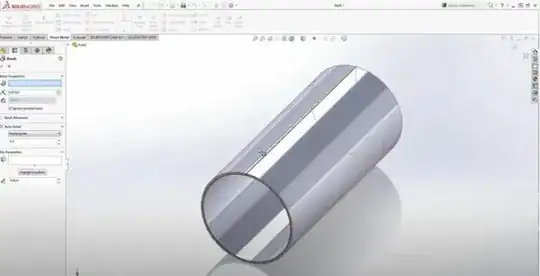
- Obtain an optically ground, pure fused quartz tube.
- Metallize the outside of the tube, so that it is covered with a couple optical layers worth of your metal of choice. (Aluminum or silver might be good candidates. Silvering can be done chemically, though not to great precision; both can be deposited by vapor deposition in vacuum. Grinding can also be done after metallization, to maintain an optically smooth and symmetrical surface.)
- Set up the cylinder inside an optical fixture to perform interferometry against its surface. This will be some kind of dual-cylindrical resonator setup, I suppose; I'm no expert on optics myself, and I would suggest consulting with one to determine a suitable setup.
- Also set up to determine polarization effects, if any. That's the most likely effect if any, I suppose: the rotation of a light wave due to the sideways flow of electrons. (You will need to separate this from the Faraday effect.)
By "optically cylindrical", I mean within a fraction of a micrometer. This is necessary to give a consistent interference pattern. One interference fringe is 1/4 of a wavelength, or around 100nm at optical wavelengths. These are very precise shapes! The exact precision isn't quite this demanding, as the pattern can be subtracted out, i.e. relative observations performed. Since we're looking for differences, we can observe extremely small changes -- fractional nanometers distance, say. I don't know what kind of effect to expect anyway, maybe some phase rotation or polarization or something -- but a clever setup can be sensitive to extremely minute differences this way.
By "optical layers", I mean a few skin depths of the material. Effectively what is skin depth at low frequencies, is the shielding depth at optical frequencies; related is the Debye shielding length (and, I forget if the latter is exactly what I'm thinking of / mean here in the first place, or proportional to it.) In metals, this is some 10s of nm.
There are three reasons for using a metallized tube:
- Current is confined to the active optical layer (give or take), so we can be sure we aren't wasting any current density elsewhere.
- It is a first-surface mirror, so we are sure to avoid optical effects in the tube itself.
- A tube is symmetrical, most suitable for inserting a magnetic field, to induce current flow in it. A solenoid coil can be slipped inside to do this, without touching the tube -- so we know we aren't introducing vibration or heating that way. We have some hope of getting an optically useful shape here as well. (Optical flats and spheres are easiest to make, and I'm kind of assuming a cylinder isn't too absurdly challenging.)
(And why fused quartz? It's a very uniform / consistent material, with low thermal expansion, and high temperature handling. It's a very mechanically ideal sort of material. It's also transparent, so will have less interaction with whatever light waves penetrate the metal layer -- but still some, which will need to be accounted for in the experimental work-up.)
Whereas a flat surface might be the easiest to make (optical flats are readily available), but it will distort in difficult-to-predict ways as it heats up, and we'd likely have to make mechanical contact with it to deliver the current flow.
On the upside, a flat could be driven with DC: we don't need to worry about inducing currents via magnetic field.
That said, perhaps we find some kind of observable effect, despite (and independent from) distortion of the surface, and so we don't care that it's got connecting cables, or nonuniform induced fields (we could induce eddy currents with a magnetic loop beside the flat surface, which makes a ring shape (image current) where current flow is maximum).
We might also consider whether the effect is microscopic. Instead of a broad laser beam and resonator, a focusing lens might be used, and a microscopic point is tested (or even imaged). This can be as small as the optical wavelength, i.e. surface details of some hundreds of nm are resolvable.
Needless to say, you will require some budget for any meaningful test. An optical bench and some instruments will be required at a minimum, and perhaps a few thousands (or tens or more) of dollars required to obtain the requisite materials and precise shapes, not to mention consulting with experts to nail down the design and figure out how to do it.
Most of all, you will require a theoretical framework adequate to resolve all these considerations. This sounds like a graduate level experiment to me. Perhaps this experiment can be set aside for now (or, performed to whatever capability you currently have, which will likely find the null result as expected), and as you advance academically, you can find literature on the subject -- perhaps someone has asked and tested exactly this question before -- or even convince your professors or advisors of the merits of such an experiment, and have a chance to do it, for real and at scale, yourself!
Good luck.

