Not all ground symbols are created equally, and are often not used precisely.
These three symbols are different.
Earth Ground means there is a connection to a big metal pole somewhere that is buried in the ground.
Chassis ground means there is a connection to the metal casing of the device.
Signal ground means the reference voltage that signals in the circuit are measured against. Meaning if we were to place a multimeter on this circuit, we place the black cable on this point when making our measurements. This can be placed in an any location, but is often the negative connection of the power supply to the circuit.
The confusion is that engineers are often lazy, imprecise, and assume that the reader will be able to discern what they mean, instead of doing it right the first time.
The only time you should be drawing the Earth Ground symbol is when there is a low resistance connection to an earthing system (big metal pole in the ground). It is almost always used as a protective feature for high voltage systems, and rarely in other situations for the purposes of this discussion.
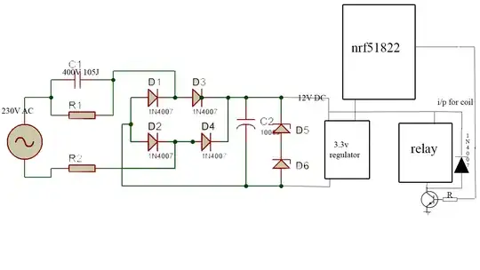
In many cases, the earth ground symbol is used when they really mean to use the signal ground. The circuit you provided is an example of this.
I think this has led you to misunderstand the '"no current through a single ground" principle'. What that answer was trying to explain is that no current will flow into a ground itself, as it is simply a label for 1 node of the circuit. It can only ever be one node. This means that if you see two or more locations in the circuit where a ground is used, it means that from this location, there is a connection to the node labelled as ground. It is functionally identical to if you created a label for the positive of the power supply, called it V+, and then replaced every wire connecting to the power supply with a connection to the label instead.
For example, this circuit:
simulate this circuit – Schematic created using CircuitLab
Could have the two nodes labelled as ground and V+:
simulate this circuit
Note: I have coloured all wires that belong to the same node the same colour.
This diagram looks a little messy, so how about we get rid of the wires, and use the labels to represent the node connection?
simulate this circuit
This is still the exact same circuit, we've just made it a little easier to read. Note that the current seems to flow into the V+ at the battery, and then out the V+ at the resistors. Similarly it seems to flow into the ground at the resistors and out of the ground at the battery.
For any circuit to work, there needs to be a power supply or battery providing a voltage between two points. Therefore drawing our battery on the circuit is a bit pointless, as we know it has to be there! So as a last simplification, we remove the battery from the drawing entirely:
simulate this circuit
Note that we have written what V+ means, it is a node that is at a voltage of 9v (due to a power source that hasn't been drawn). Also, since we have not been told what the 9v is in reference to, we can assume it is in reference to the node labelled ground. (remember the labels we had on the battery before we removed it from the drawing).
If we now look at our final drawing, it appears that there is current flowing into a single ground! But we now can see that this is because of the label of the node, which is connected to our power source which has been omitted from the drawing.
I would suggest that the 'one ground means that there is no current flow into it' is misleading you. You need to consider what the ground label means. Is it only showing you what node is used for the black wire of the multimeter? Or does it mean the negative side of the power source in use? What it means will decide whether there is current flow into it or not.
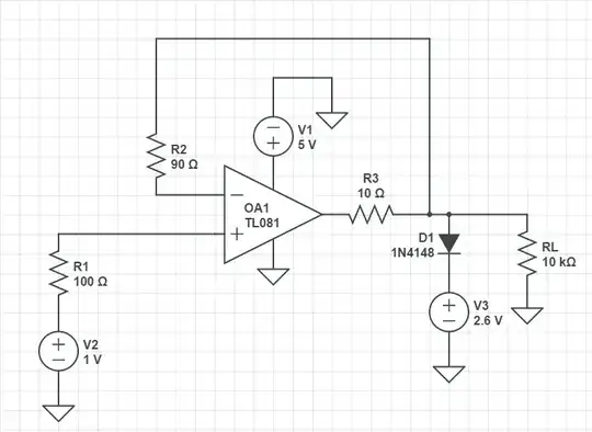
simulate this circuit
Looking back at this circuit, what does the ground mean here? Is it showing us the negative side of our power source? Well our battery has been drawn into the circuit, and if there was another power source that hasn't been drawn, we would see another label that would tell us about the positive side of the power source. So it is safe for us to assume that this is only a reference point label, and therefore we are considering that the connection between the resistors is the location in the circuit which is '0v', which we will measure all our voltages with respect to. Since it is a reference label, there will be no current flow into it!


