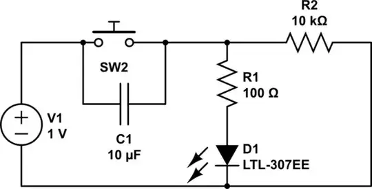
This is not a good debounce circuit.
One problem is that (at least ideally) the switch and its connecting wires have a resistance of zero. This means that the capacitor will instantaneously discharge when the switch is closed. (In practical terms, also, this rapid discharge could even be bad for the switch contacts or the wiring, if there is a high enough voltage on the capacitor and it has a high enough capacity.)
A capacitive switch debounce should slowly charge the capacitor when the switch is in one state, and slowly discharge it when it is in another state. The RC constant doesn't have to be the same, but it should be something nonzero. The circuit has resistors that control the charging of the capacitor; it just needs a resistor in the switch loop to discharge it gracefully.
Another problem with this circuit is that the LED is only off if the circuit has been on for some time, such as if the circuit has existed since the beginning of time with that same voltage source. But what if, at time \$t = 0\$, the voltage source has been 0V and suddenly jumps to its voltage? At that time, the capacitor, which must have been empty, begins charging. While it is charging, current flows and the LED will light up briefly and then go dark. (Well, maybe not, because your source has only 1V, but that's another story).
In CircuitLab, you can distinguish these two situations in the "Time Domain" simulation. You can either "Skip Initial" or not. The solver can either pretend that the circuit has existed in the given state for all eternity until the time \$t = 0\$, and start solving it from there. Or it can solve it from the point of view that the circuit just came into existence at \$t = 0\$ and the voltage sources spring into life, the capacitors are empty, and so on.
One final consideration here is that the circuit only lights a LED, so switch bounce is basically moot, unless the LED is shining on some optical detector where the switch bounce turns into a glitch in the signal. If the LED's job is to just provide a pretty light, then your eye won't even be fast enough to see the switch bounce.
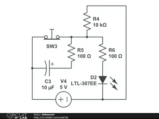
Here is a time domain simulation of the circuit (after changing V1 to 3V). What is plotted is the LED current. Important: the Skip Initial parameter is set to Yes, so we can see what happens when the capacitor is initially empty and the voltage source energizes to 3V. This is all with the switch in an open state.
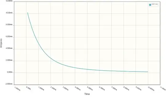
As you can see, current surges through the LED and then dies down. If your intent was that the LED is strictly controlled by the operator via the push button, then your design does not implement your intent one hundred percent.
With regard to the comment below, suppose that the aim is to actually drive a microcontroller pin (everything running at 5V). Firstly, we can do that without any capacitance and handle the debouncing in software by sampling the pin at a reasonably low rate.
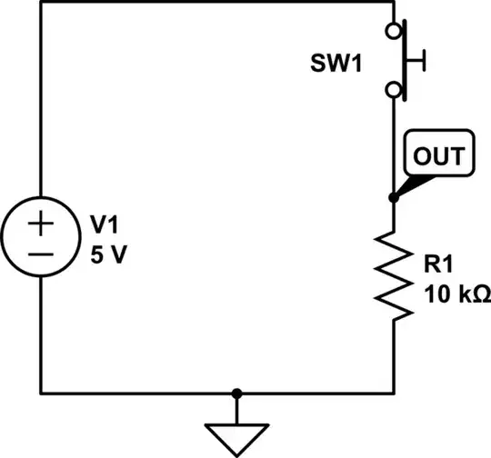
simulate this circuit – Schematic created using CircuitLab
When the switch is open the output is pulled to 0V by the pull-down resistor. When we close the switch, the voltage at the top of the resistor rises to 5V. This output can be regarded as a signal. We are interested in the low frequency component of the signal: relatively slow switch presses. We want to reject high frequencies, like switch bounce. To that aim, we can add a passive, one-pole RC low-pass filter:

simulate this circuit
Now when the switch closes, the voltage rises gradually as the capacitor is charged. You can see this in the time domain simulation:
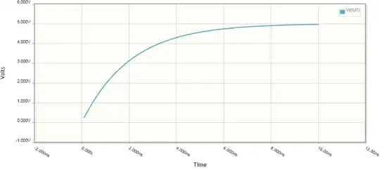
When the switch is opened, the capacitor will discharge through R1 and R1, gradually dropping the voltage back to zero. The capacitor basically follows the voltage of R1, but with lag due to having to charge through R1, and discharge through R1 and R2. (Note that the discharge is twice as slow as the charge!)
The microprocessor input senses the voltage with high impedance, so we can ignore its loading effect and not even show it on the diagram. We cannot do this in the case of the LED because it requires current which our circuit must supply. That current flows through our resistors and develops voltages that we must account for: in other words, it has "loading effects".
This type of circuit works even better if we feed the output to a Schmidt trigger. A Schmidt trigger is a kind of buffer for digital signals which shows hysteresis similar to a thermometer. Its output goes high when some high input threshold is exceeded, and falls low when a different low threshold is exceeded. For instance, it might go high when the input goes above 3.5 volts, and only go low when the input falls below 1.5.
So even if the capacitor allows through some noise that could still cause some small flipping back-and-forth near the crossing of an input's threshold, the Schmidt trigger will reject that.
Suppose we want to debounce the LED with a capacitor? The problem is that the resistances end up being too low due to the need to supply current to the LED. If we just use the same circuit and make the resistors smaller (and the capacitor larger by the same factor), we end up with something which wastes power. The way to do this is to use a small signal loop to handle the switch, and debounce it, and then use the voltage to control a transistor which dumps current into the LED.
Though debouncing a LED might be useless, if we make the resistors and/or capacitor large enough, we can obtain a nice behavior: that of the LED slowly fading on when the button is pressed and held, and fading out when it is released.
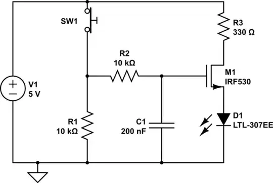
simulate this circuit
This is the same circuit as before: the "out to microcontroller" node now connects to the base of an n-channel MOSFET which drives current to the LED. The MOSFET "buffers" the debounce logic from the LED driving. The debounce circuit isn't disturbed by the low impedance of the LED, and the LED is not starved of current by the high impedances in the debounce circuit.