2

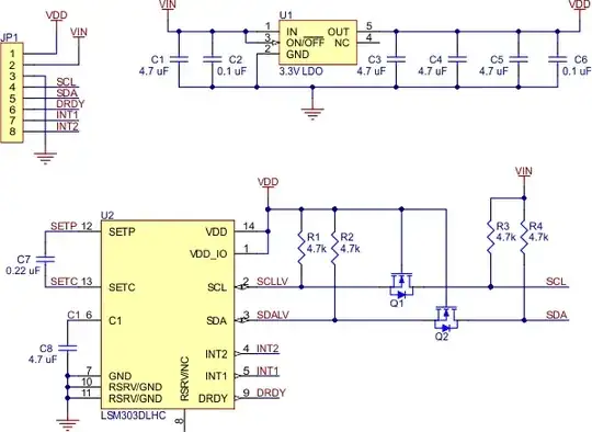
i want to understand the thought process and ideas behind these:

see the schematic

http://www.pololu.com/catalog/product/2124

1 - what is the n-FET and diode (Q1 and Q2) component means?

2 - why the 4.7kOhm resistors used instead of 10kOhm like in the datasheet here (also applicable to other circuit,this is just an example to help me understand) Datasheet

3 - how designers verify that the component values used will yield the desired result? i mean they are only provided with IC and its datasheet,sure they need to do simulations to verify the circuit. do they model the IC?How's the simulation done for e.g?

4 - any tut/books to help me understand better how to connect IC with external components?like from a pin of an IC with sensor/op-amp,choose values,what to consider, how to verify etc. in short how to use the IC pin as a driver or input from other components.

enter image description here

Passerby
  • 72,580
  • 7
  • 90
  • 202
Reuk Reuk
  • 21
  • 1
  • @Passerby : the app hints sure help,but if i want to connect the pins with other components like bjt,etc instead of what being recommended in datasheet, is it possible?if yes how do i simulate the entire circuit? – Reuk Reuk Apr 24 '13 at 00:17
  • For good books, have a look at this question and the answers - [Basic Electronics Book](http://electronics.stackexchange.com/questions/616/basic-electronics-book). Also read datasheets as Passerby mentions, and app notes - there is lots of excellent free material out there. Another source is stuff like the MIT (and other places) video lectures - they have an excellent series on electronics theory, signals and systems, DSP, etc - see their profile on You Tube. You can even sign up for online courses if you are very keen (or siimply work through the material yourself) – Oli Glaser Apr 24 '13 at 01:04

1 Answers1

2
  1. The Diodes are the Mosfet body diodes. They are internal, and part of how the mosfet works. The Mosfet themselves are used as simple level shifters on the I²C clock (SCL) and data lines (SDA) enable I²C communication with microcontrollers operating at the same voltage as VIN (2.5–5.5V)

  2. i2c, an open drain protocol, requires pull-up resistors. The value of the resistors are defined based on bus capacitance, length, i2c frequency, desired rise/fall times, etc. Or more simply, standard values are chosen. 4.7kΩ works just as well as 10kΩ, for general usage.

  3. Which components? The Caps or Resistors? Generally, the datasheets for the ICs that are being used will dictate what they need, and have general guidelines or reference designs in them. And often formulas for certain variables. Notice Section 4 of the Compass datasheet, keyword nominally. The chosen capacitors should be around those values, don't need to be exact (and most ceramic caps have a high +- tolerance rate). The schematic section 4 as well, is essentially what the Pololu board copies, except for the mosfet level shifter.

    The C1 and C2 external capacitors should be low SR value ceramic type constructions (typ. suggested value 200 mOhm). Reservoir capacitor C1 is nominally 4.7 μF in capacitance, with the set/reset capacitor C2 nominally 0.22 μF in capacitance. The device core is supplied through the Vdd line. Power supply decoupling capacitors (C4=100 nF ceramic, C3=10 μF Al) should be placed as near as possible to the supply pin of the device (common design practice).

  4. That question is very open ended. A general electronics textbook would help. I personally learned by reading datasheets.

Passerby
  • 72,580
  • 7
  • 90
  • 202