I came across this schematic:
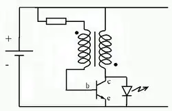
What do the dots in the transformer indicate?
Those are phase dots. They refer to the 'start' of the winding based on a predetermined winding direction (CW or CCW). This allows you to tell at a glance what 'polarity' the windings have so you can figure out how the current will flow.
The dots tell you the relative orientation of the windings. Without them, you don't know the polarity of the voltage coming out of the secondary with respsect to the primary. In many transformer applications that doesn't matter, but when it does the dots need to be shown on the schematic.
The way to read the dots is to imagine current going into the primary at the dot. That causes current to go out of the secondary at its dot. If the transformer has a 1:1 ratio, then you can imagine that for differential mode signals there is no transformer, just a connection between the two dot ends accross primary to secondary, and the two not-dot ends. Of course this doesn't hold true for the common mode part of the signal since that is isolated, but it might help visualize how to interpret the dots.
If the dots were on the same side, your circuit schematic would have be drawn with crossing wires, like this:
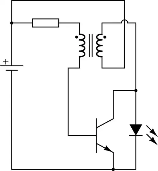
simulate this circuit – Schematic created using CircuitLab
By adding the dots to the coils, we clarify that the orientation of the coils is important. And by allowing ourselves to put the dots on either end, we gain a the freedom to rearrange the diagram to suit our convenience, such as not to have crossing wires. So, it's not a different kind of transformer; only a notation.
So why do we sometimes not see dots in transformer schematics? That just means the orientation is not specified, which means that it either it doesn't matter in the application, or the schematic has an error: the polarity actually does matter, but the dots were mistakenly omitted.
A common example where it doesn't matter is a power transformer which steps down AC and feeds a bridge rectifier. The transformer will work properly whether it inverts or preserves phase. By contrast, your Joule Thief circuit will not work properly if the transformer is wired incorrectly.