I have a circuit that measures soil moisture but I am not able to understand how it works. Should we use copper plates or probes in the circuit? Is the circuit measuring the capacitance or resistance between the probes?
I have a circuit that measures soil moisture but I am not able to understand how it works. Should we use copper plates or probes in the circuit? Is the circuit measuring the capacitance or resistance between the probes?
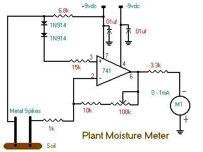
This is not a great circuit for a variety of reasons. It is measures the current that leaks between the two probes with a reasonably constant voltage applied. For reference, here is the circuit again (this is what I'm answering even if the question is edited later):

The opamp is used as a inverting amplifier. It looks like the intent to hold the + input two diode drops below the positive supply. There should be a resistor from the bottom of the diodes to ground to guarantee the diodes are always forward biased. This circuit is relying on the opamp input bias current, which is a bad idea.
Due to the feedback, the opamp will keep the - input at this bias voltage produced by the diodes. Let's say the diodes drop 600 mV each, so that will be 1.2 V below the top rail, which comes out to 7.8 V roughly. The 1.2 V appears accross the spikes. More moisture means more current at the same voltage. Forget about R3 (put component designators on your schematic!) for now. The current thru the sensor will flow thru the feedback resistance, which will cause a voltage accross it. The opamp output will be the 7.8 V from above minus the voltage accross the feedback resistance. The meter will therefore read lower for high moisture and higher for low moisture.
Overall, this is a pretty crappy circuit. I already mentioned the reference voltage depends on the opamp having sufficiently high input bias current. This won't work with better opamps that have much higher input impedance. Other problems with this circuit is that it keeps current constantly running thru the probes, and the current only goes in one direction. That means corrosion and plating effects will by assymetric, and there is no cancellation of any battery effect.
I have had to detect moisture before, and there are much better ways. One I found to work very well is to use two microcontroller pins that can each be high or low outputs, have high or low weak pullup/down, or A/D inputs. With this setup you can take 4 separate readings. One pin is always driven either high or low, and the other pin is weakly pulled in the opposite direction. This gives you 4 separate combinations. By combining the voltage drop measured from all 4 readings you get no net DC current, stray external offsets cancel out, and the battery effect cancells out. In addition, the total current thru the probes is very small since you only need to drive them a few µs each reading. Most of the time the probes are not being driven at all, even if you take a complete suite of readings 10s of times per second and apply a little low pass filtering.
The circuit measures the resistance of the soil between the probes. The size and shape doesn't matter so much for a rough reading, so spikes or plates will work. If you want to try and calculate the resistivity of the soil, then two square plates would probably be best.
The potentiometer can be used to adjust the gain, and set the zero point to whatever reference level of moisture you wish. The circuit is a differential amplifier, and works by amplifying the current passed between the probes. Since the diodes will provide a very small drop (maybe ~150mV or so) the non-inverting input will always be at a little lower than the probe plate, so it is this voltage that is across the soil and the 1k resistor.