1

I'm interested in building an LED digital thermometer with 3 or 4 large 4"/100mm 7-segment LED display digits (for example, Kingbright SA40-19EWA). There are plenty of kits available which come with smaller LEDs (e.g Conrad, Canakit). My question is, what's the likelihood of success attempting to use any of these kits to drive larger LEDs instead of the ones they're supplied with/designed to work with? And if it seems infeasible, would I be better off starting off from an Arduino-based thermometer design instead? (Although my initial reaction is that an Arduino would be overkill.) Any other pointers/advice welcome.

The main issue to overcome would seem to be that the large LEDs typically need 7-8V, while 2V is more typical for smaller ones (but maybe some kits are amenable to suitable modification by, say, changing a few resistor values). Of course there's also other things to worry about such as common cathode/common anode and the mechanics of replacing the original PCB-mounted displays with wires to the bigger digit components which might influence choice.

Fizz
  • 14,355
  • 2
  • 43
  • 97
timday
  • 133
  • 1
  • 6
  • 1
    I don't know anything about this kit or Arduino, but I built my own large 7-segment display that is driven from an ATmega328p (the AVR MCU that many Arduinos are based around), uses very little current, and only needs 5V... that is, if you are willing to try and build something instead of buying kits. Although, I bet the kit could be modified slightly to work with my display as well: http://www.projectsbykec.com/projects/miscellaneous/large-led-lit-7-segment-display – Kurt E. Clothier Apr 22 '13 at 22:34
  • Wow! Thanks for all the great info here (answers and comments); much appreciated. Will have to consider a bit more how I'll proceed next before I accept an answer, but strongly leaning towards getting the display driver end sorted first (especially as I've just discovered 20cm high 7-seg displays are available :^) and then working back to whatever controller/SW/GPIOs it takes to do the job, rather than trying to abuse the heck out of something more specialized that's actually designed for something different. (And I'm happier with SW than I am with HW). – timday Apr 23 '13 at 19:13

3 Answers3

3

TL;DR: The kits you link to will not work with the big 7-segment display you propose. In my personal estimation, the complexity of the ICL7107 design (the Canakit and the Contrad kits are based on this chip) and the Arduino design will roughly be similar, if you build the simplest possible design. However, either design in the simplest version might not you to use the referenced 7-segment display at full brightness, and in fact the referenced 7-segment display might be too dim. Therefore, (depending on the display), you might as well go with the Arduino design, because the Intersil chip is really designed to run the 7-segment displays directly, something you cannot do if you want full brightness.

The large 7-segment LED display

The characterists of the 7-segment displays will in large part drive your design. There are two characterisits of concern here:

  • The foreward voltage drop of each segment. If the Vcc supplied to the LEDs is less than this value, the LED will not turn on.
  • The maximum forward current across each segment. To display at maximum brightness, you will want to supply something close to this value.

The datasheet I found for the Kingbright SA40-19EWA references two types of large 7-segment displays:

  • High Efficiency Red: Forward V / segment: 8V typical, 10V max. Maximum forward current is not referenced, but the test conditions suggest that 20mA is typical. The charts on page three imply that 30mA is maximum.
  • Super Bright Green: Forward V / segment: not reference. Maximum forward current: 60mA, suggests that 40-50mA current would be appropriate to drive it at full brightness.

If the above characteristics are correct, then you could build an ICL7106/ICL7107/ICL7107s-based circuit for the red 7-segment display, but not the green one if you want to run at full brightness.

Using the large 7-segment display with pre-packaged kits

The Canakit you link to is designed to run off 5V. Given that the forward voltage of the Kingbright SA40-19EWA is 8-10V, the result is likely to be a non-working digital LED thermometer. These kits are also not designed for the kind of current the super bright 7-segment display needs to be on at full brightness (, see below), and this is a problem inherent to the chip at the heart of the circuit, the ICL7106/ICL7107/ICL7107s

Building a new ICL7106/ICL7107/ICL7107s-based circuit from skratch

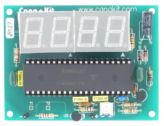
Using the ICL7107, the temperature probe signal is compared to reference voltage, and the result is processed by the ADC on the ICL7107 and then output on 7-segment LEDs. The ICL7106 runs off +15V, so you could use the 8V LEDs with this design. As you can see from the kit image there are not a lot of supporting components you need:

enter image description here

Note, however, that ICL7106/ICL7107/ICL7107s can only sink around 16mA of current from the 7-segment displays. This means that you will not be able to drive the super bright display at full brightness from the Intersil chips, and given the nature of ICL7106/ICL7107/ICL7107s, interfacing them to a driver that could allow more current from the 7-segment displays may be difficult.

Modifying a reference Arduino kit

The Arduino kit you referenced will likewise need extensive modifications in order to a) support the voltage required by the 7-segment display you reference and b) supply the current needed to run the large 7-segment display at full brightness.

Building a new Arduino temperature display from scratch

For an Arduino-based design, (assuming, at first, the underpowered design as above), you should have enough pins to do everything. The cheapest Arduino (Arduino nano) has 22 GPIO pins, of which you'd be using 1 to read the temperature sensor. This will leave you with 21 pins to drive your 7-segment LEDs. The way such displays are usually constructed is by multiplexing the LED displays (for instance the MAX7219 works this way). Specifically, what happens is first the first 7-segment display is drawn to display the correct digit, then the second, and then the third. If the cycle happens at more than, say, 30Hz, then the result is a seamless display as far as the human eye is concerned. To do this, you will only need 8 GPIO lines to paint the segments plus 4 GPIO lines to select the 7-segment display. The alternative (non-multiplexed display) is not possible on Arduino nano, since you'll need 8 lines / 7-segment display times 4 displays = 32 GPIO lines. It would be possible to do this on a beefier Arduino, but that will cost more. On the Nano you could use a shift register, or some other serial-to-parallel IC, such as the 74HC595 to give yourself more pins, so to speak.

The LED you are looking at is common anode, so you could use the Arduino to drive it directly buy sinking the LED current into the GPIO chips. At the same time, the LED you reference can take up to 320mA of current per segment, so if you want to drive it at full brightness, the Arduino solution will require external circuitry, such as a darlington array, as described here, for instance.

With the Arduino design, there will be some programming involved. You'll have to write a small program to read the temperature, and then to drive the LEDs. If you want full brightness, the Arduino will control discrete transistors (ugh) or a darlington array which will drive the LEDs directly. So you'll have to write code (or borrow one from an existing Arduino project) for converting your temperature data to 7-segment control lines. It isn't particularly difficult, but does take a bit of time. Additionally, combining this code with the multiplexing code is adds to the code complexity, but there are Arduino libraries for doing this.

angelatlarge
  • 3,611
  • 22
  • 37
  • Such designs are almost always multiplexed at the display-generation level, so pin count would not ordinarily be an issue. Using a discrete drive for each larger LED segment could allow the use of low side drivers only, slightly simplifying things, but it's not as if the current is so high that needing both high and low side drivers to allow a multiplexed large segment display would make things that difficult. – Chris Stratton Apr 22 '13 at 22:00
  • @ChrisStratton You are right, I should add a note to that effect. I mean that's how I build _my_ designs, but I was going for simplicity. But very good point, thanks. – angelatlarge Apr 22 '13 at 22:07
  • Actually, the datasheet mentions 320mA, but only at 1/10 duty cycle, under Absolute Maximum. The Absolute Maximum continuos current is 60mA per segment, but the recommended is 20mA. – Passerby Apr 22 '13 at 23:04
  • @Passerby I was in the process of correcting that. That was max peak – angelatlarge Apr 22 '13 at 23:04
  • @Passerby Where do you see "recommended"? I see 60mA max for Green – angelatlarge Apr 22 '13 at 23:05
  • The 60mA is under Absolute Max. The If = 20mA is used in all the standard ratings for Electrical / Optical Characteristics at TA=25°C, right above it. I take that to be the general usage condition. – Passerby Apr 22 '13 at 23:08
  • @Passerby But I think that references different products: the test conditions are given for the "High Efficiency Red" device, whereas the Maximums are for the "Super Bright Green." Or did I miss something? – angelatlarge Apr 22 '13 at 23:11
  • @angelatlarge The datasheet is garbage. That's what. The rest of the datasheet references High Efficiency Red, including the graphs. A different wavelength version of the same part: http://www.kingbrightusa.com/images/catalog/SPEC/sa40-19srwa.pdf for comparison. And their website gives intensity ratings, at 10mA If. – Passerby Apr 22 '13 at 23:15
  • @Passerby Nice detective work. Must be a copy-and-paste error on their part. Since the luminous intensity linearly increses with forward _I_ (at 20mA it is half of what it is at 40mA), I assume that for maximum brightness, you'd want something closer to 60mA than to 20mA, and I also assume that continous forward I under 60mA is fine. Do you disagree? – angelatlarge Apr 22 '13 at 23:24
  • Only when the brightness is needed, at the expense of led life. I'm a bit skeptical of the thing putting out 600,000 ucd at 60mA too. But I'm still wondering how the odd internal setup of each segment works (4 series sections of 2 parallel leds). – Passerby Apr 22 '13 at 23:32
1

If you have a board which is designed to drive a 7-segment LED display, it should probably not be too hard to generate logic-level signals corresponding to the display segment and common wires. If you determine that you have e.g. a four-digit common-anode display with a resistor on each of the segment pins and can tap at the driven side of each segment resistor, the common cathode wires should be readable (possibly with a resistor divider to ground) as logic-level signals to indicate which digit is being wired, and the driven sides of the resistors should be usable as logic-level segment wires to say what is being displayed on that digit.

I would suggest that depending upon the exact drive waveforms, it may be possible to then use four 8-bit latching display drivers to grab the states of the segment wires when their common sires are driven, and then use their outputs to drive your nice big displays. Even if the original displays are multiplexed, using latching driver chips would allow the segments to be driven continuously with 1/4 of the peak current that would be required with multiplexing.

supercat
  • 45,939
  • 2
  • 84
  • 143
1

The answer to either modifying an existing one, or a microcontroller based solution (like the linked arduino one), is Transistors. Transistors can be used for handling the voltage difference, and handling any current difference.

The first is modifying an existing kit. This would vary based on the kit. Using one of the ICL7106 kits as an example, you would need a transistor for each segment pin. This is because the ICL7106 has a pin for each segment, and is controlled individually (Open Drain). You cannot drive the LED display with 8v, as it would fry the input pins of the ICL. Given 3 Seven Segments plus 1 3 Segment usage, that's 24 transistors, plus 24 pull up resistors, and 24 current regulation resistors for the LED segments.

Modifying the kit for a different voltage display is not as simple as I thought, it would require inverting the open drain of the ICL7106, and would be much easier with a common cathode display. The schematic I had made would result in the inverse on the display (A segment that should be on, would be off while the others were on. See here for that.

The Ardunio solution uses scanning to control the 4 segment displays, where only one led is light at any given time, but fast enough that you can't tell. And it does so by multiplexing to reduce the pins needed. The 4 anodes of Displays are individually controlled, while all the segment cathodes are tied together. So only 4 + 7 transistors are needed, as well as 11 base resistors, and 11 current regulation resistors.

enter image description here

Of course, both schematics are simplified, simply because it takes a lot to draw them. The dotted box represents each Led Display, and each diode represent an individual Segment. (Assumptions: 9v Source, 8V Forward Voltage, 20mA current draw).

Passerby
  • 72,580
  • 7
  • 90
  • 202