3

I am trying to run some indicators/flashers on my own made bicycle. I have attempted ready-made automotive flashers but have found the lights don't draw enough current for the 2-wire ones and get weird behaviour. With the 3-wire relays types I have been unable to get them to stay in sync when the hazards are activated (both left and right activated at the same time)

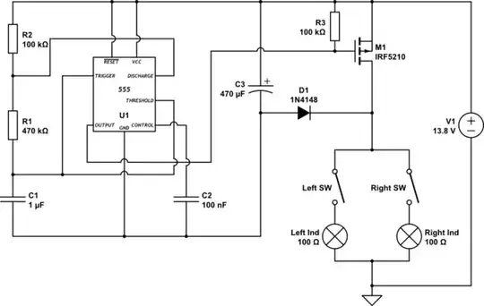
I have attempted to make a circuit of my own using components I have to hand.

schematic

simulate this circuit – Schematic created using CircuitLab

Given the above circuit do my mosfets need any inline gate resistors or pull up/down resistors?

Is there anything else in the circuit I have overlooked or won't work as intended?

To further complicate things the switches are part of a switch cluster that shares a common positive and the lights are part of a light cluster that shares a common negative meaning I cannot alter the circuit outside of the switches and lights.

Update: Thank you for all the answers. Based on them I went with a simpler solution of using a DPDT relay driven by the 555 timer:

schematic

simulate this circuit

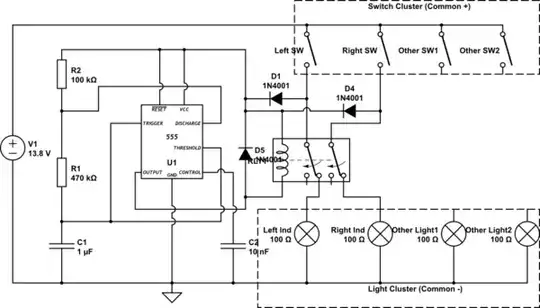
No need to worry about driving FETs or transistors, provides a satisfying click-click and I connected the indicators to the NC-connected pins so that the indicators come on as soon as they are switched.

Scott
  • 286
  • 3
  • 10
  • You really should put a fairly large bypass capacitor (about 47 uF) on the Vcc and GND of the 555. And maybe a TVS or zener to protect the circuit from transients. – PStechPaul May 09 '23 at 00:50

2 Answers2

4

The MOSFETs need to be connected in common-source configuration. And you only need one of them. No need for a pull-down on the mosfet for basic functionality, since when the gate is not driven - when 555 is off - the lights have no power either. But to protect the MOSFET against electrostatic charge building up on the gate, a pull-down would be nice to have.

schematic

simulate this circuit – Schematic created using CircuitLab

C3 charges when the bulbs are in the dark part of the cycle, and then powers U1 when M1 conducts. That way you can still use just one MOSFET, and the circuit works pretty much like an old-style blinker would - it has only two external connections :)

winny
  • 13,064
  • 6
  • 46
  • 63
  • @Kubahasn'tforgottenMonica I appreciate the addition circuit where lights share a common negative but I also have the issue where the switch cluster shares a common positive. The new circuit will not work for me as this setup would pulse other systems running off the same switch cluster. I apologise I didn't make this clear in my initial question as I didn't think it was relevant. You have technically answered my question about gate resistors requirements so I am happy with your answer. I may be better off running the 555 output via a simple BJT transistor and a DPDT relay given the setup. – Scott May 06 '23 at 21:02
  • @Scott You need to put all those limitations into the question. Otherwise it wastes your and our time :) – Kuba hasn't forgotten Monica May 06 '23 at 21:53
  • I have updated the question and agree wholeheartedly that giving all the information is vital to not waste anyone's time. Hindsight is a wonderful thing, I didn't know it was relevant to the question until you showed some optimal arrangements of the circuits and realised my setup had limitations. – Scott May 06 '23 at 22:02
2

The MOSFETs don't strictly need inline gate resistors, but your original circuit doesn't drive them fully on either. This could lead to high power dissipation in the FETs and overheating.

If you exchange the position of the FETs and the lights, then the FETs will be grounded, and the VGS can be driven strongly. If your supply is '12V' and you have FETs that can take VGS = 20 V, then all is OK. However automotive '12V' can have 40 V spikes (worst case) and other transients -- you probably need some protection in your circuit for that -- for the 555 as well as the FETs. If you add an R (say 100 Ω) where the diode's cathodes join and a 15V zener to ground, you will protect both the 555 and the FETs VGS.

Note that normally flashers turn on the instant the switch is closed -- your circuit may not do that; you can fix this by connecting C1 between trigger & VCC rather than trigger and GND.

jp314
  • 18,395
  • 17
  • 46
  • Regarding the FETs do you feel like overheating will be an issue given they will be flashed on and off for short periods of time and only run some LED clusters and are unlikely to drive more than 1A each? While using automotive components there should be nothing to generate 40V spikes such as alternators etc. The switching and lighting gear is run from a 60V batt run through a 13.8V voltage regulator. I don't think the protection circuit is needed but a nice to have here. I cannot swap the lights and FETs positions due to light and switch clusters sharing common +/- connections. – Scott May 07 '23 at 10:11
  • your suggestion to change c1 from GND to VCC. Is this what you mean: https://ibb.co/Pm4N4z4 – Scott May 07 '23 at 10:17
  • Yes; if it is polarized (electrolytic), the + now goes to VCC – jp314 May 07 '23 at 22:12