10

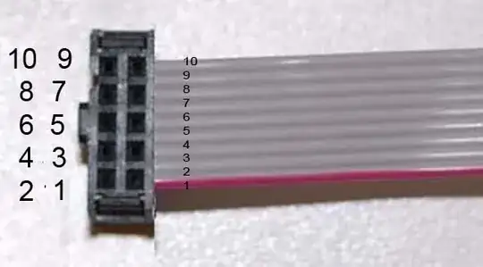
I have a PCB with documentation. In the documentation, there is referred to specific pins of several jumpers and connectors. On the PCB however, there isn't a label or so for which pin has what number. I need to figure out which pin has which number, so that I know the function of each physical pin.

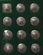
I noticed all connectors have all pins with a rounded tin pad, whilst one pin (either the first or the last when counting from right to left) has a square tin pad:

enter image description here enter image description here

Is it some kind of convention which number this pin has? After that, how to count the other pins?

6 Answers6

15

Normally the square pad is pin 1.

The left picture looks like a DE9 connector - on that connector family, the pins are numbered along the row from pin 1, then the second row is numbered in the same direction, like:

   5  4  3  2  1
    9  8  7  6

For the rectangular array in your second picture, pins may be numbered either row by row, or column by column, depending on the designer's whim.

You may find pin numbers on the connector itself, or on the mating connector.

Peter Bennett
  • 57,014
  • 1
  • 48
  • 127
5

Generally, pin 1 is given a unique shape (often square).

Beyond that, numbering tends to be non-standard - you'll need to check the manufacturer's datasheet for the specific connector in question.

Adam Lawrence
  • 32,921
  • 3
  • 58
  • 110
3

Generally, the 'different' pin is pin 1. On the first picture, that would be the square pad, top right, second pic square pad top left. I would think it then numbers across the top, and then loops down to the row below it. On the first pad it would be right to left, second left to right, assuming the pictures are oriented correctly.

The first picture looks very similar to a serial DB9 connecter, and this supports my theory on numbering. Look at it as if you were plugging in the male connecter to the board, and the numbers match..

The second picture I have nothing to base my assumption off of but experience.

Attack it with your multimeter and see where you have continuity before soldering anything.... I would have expected a diagram that came with the board. From there I would try to contact for the company that provided you the board.

Butters
  • 317
  • 2
  • 11
  • 1
    On D-subminature connectors (like DE-9 serial connectors), both rows are numbered in the same direction. In the picture, the top row is numbered right to left, 1 - 5, wile the bottom row is right to left, 6 - 9. – Peter Bennett Apr 22 '13 at 21:30
2

From my experience as layout designer, pad with different shape is pin 1. You have to read datasheet or refer to standards. In general take attention in cable tipology. For example, in ribbon flat cable connectors, as micromatch, mic, DB, because the numbering does not occur in ascending order along the line, but according to an order staggered row / column. In fact, assuming an increasing numbering of the ribbon cable, the wires on the connector are arranged in a staggered manner on terminals.

enter image description here

enter image description here

Neutrino
  • 455
  • 3
  • 6
  • I believe the annotation on the first image is incorrect. Pin 1 should be on the same side as the polarizing key. This image shows up on search engine results for "ribbon cable pin numbering" and is misleading. (Example: https://superuser.com/q/957715) – JYelton Jan 31 '23 at 19:32
1

I've always seen pin 1 being the square pin and this applies to several jobs I've been in. I'm not saying it isn't a rule that is universally adopted but I'd be a little surprised if it isn't pin 1.

I think pin 2 will be on the row below this square pin - this is based on the type of connector that I believe it to be. Odd numbers on this occasion, will be on the top row methinks. The black PCB connector may be columned into A, B and C but I've seen triple row connectors with the top three being numbered 1, 2 and 3 left to right

Andy aka
  • 434,556
  • 28
  • 351
  • 777
1

From my experience (although limited), the square pad is pin 1. It will then proceed sequentially on the same line.

The black pcb, it looks like the numbers increase down, and then goes to the next column.

efox29
  • 11,827
  • 9
  • 56
  • 102
  • I think pin 2 will be on the row below this square pin - this is based on the type of connector that I believe it to be. Odd numbers on this occasion, will be on the top row methinks. The black PCB connector may be columned into A, B and C but I've seen triple row connectors with the top three being numbered 1, 2 and 3 left to right. – Andy aka Apr 22 '13 at 20:22