6

I am stumbling upon a very strange situation unless I did something totally wrong in my measurement setup. Speaking of it, I've installed an acoustic measurement tool (REW) and measured for testing purposes an RC lowpass filter by using two mono audio jack cables attached to my external audio interface.

When I measure the frequency response of the audio interface itself (input connected to output), I get an almost flat curve:

Frequency response - Loopback

So far, everything as expected. Actually I expected that the curve would go down at the lower end of the spectrum. But nowadays you can get apparently real good interfaces for a decent price.

Next I measured the following circuit with R = 47.2 Ohm and C = 957 nF, which I measured with my DMM and got the following curve:

Frequncy response - RC lowpass

The curve above tells me that the 3dB cuttof frequency is somewhere between 680-700 Hz, which totally not matches the calculated value of around 3.52 kHz.

So what am I doing wrong? Or what am I missing? It seems as if somewhere in the chain a hidden capacitance is existing.

P.S: Here is my breadboard setup:
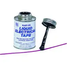
enter image description here

abg1984
  • 111
  • 4
  • 3
    What's the output impedance of the driving source? The output impedance needs to be added to the 47.2 ohm resistor value in order to calculate the cut-off frequency of the filter. – qrk May 02 '23 at 19:11
  • As per datasheet it is 430 ohms. – abg1984 May 03 '23 at 12:23

2 Answers2

5

So what am I doing wrong? Or what am I missing? It seems as if somewhere in the chain a hidden capacitance is existing.

You haven't factored in the output impedance of your signal generator. The hidden component is the output impedance of the signal generator. It might be 600 Ω for audio. I've even come across 300 Ω output drive impedances and, 50 Ω is quite often used.

You can prove this by hooking your receive line to your output line loaded with the RC network you mentioned you used.

Andy aka
  • 434,556
  • 28
  • 351
  • 777
  • The spec says 430 ohm line output and 60k ohm line input. When I add them to my calculations being the output impedance in series with the filter and input impedance as a load at the filter output, I end up with around 336 Hz cutoff. That's still almost the half what I measure. What else can I measure or factor in to verify the measured cutoff? – abg1984 May 03 '23 at 21:17
  • As I said in the final sentence of my answer. – Andy aka May 03 '23 at 21:35
  • Sry, maybe it's my electronic inexperience but I didn't get this one. So I have my source connected to the filter input and filter output to the line input of my interface. How can I now estimate the hidden values from the frequency response? – abg1984 May 05 '23 at 18:17
  • 1
    You have your source connected to your filter input, nothing connected to the filter output and, the line input of your interface connected to the filter input (where your source is). Then, what you plot is how the source voltage degrades due to the loading effect of the filter @abg1984 <-- if there is no degradation then maybe you have got dodgy resistor or capacitor having a different value to what you thought. – Andy aka May 05 '23 at 18:27
  • Ok, many thanks. I'll try this one. – abg1984 May 06 '23 at 12:03
4

Your audio output connector does not have zero output impedance, and your audio input does not have infinite input impedace.

The audio output will have some components such as series capacitor fot AC coupling (DC blocking), series resistance for protection such as for limiting current and providing isolation from highly capacitive loads for stability, maybe even a small capacitor of few tens of picfarads to ground for extra RF shunting to ground.

So as per your measurements, the output impedance of the audio port would be approximately 220 ohms.

The RC filter made with 47 ohm resistor and 1uF capacitor are not suitable values for audio interfaces.

You should try at least 470 ohms and 100nF, preferably 4700 ohms and 10nF.

As the audio input will also have some input impedance which will load the output of the RC filter, it may not be a good idea to go up to 47000 ohms and 1nF.

Justme
  • 127,425
  • 3
  • 97
  • 261
  • 1
    Hmmm, ok, learning some valuable lessons. The datasheet says 430 ohms line output, 60k ohms line input. So, is there a way to measure it without changing the values? What happens if I put an opamp buffer at the output of the filter? By the way, how did you read the output impedance from the graph? – abg1984 May 02 '23 at 21:11
  • Buffer at filter output is irrelevant because the filter loads the output. If you have capacitance C and cutoff frequency, you can calculate the resistance R. Same way you can use different resistors on output and measure what effect they have on output. – Justme May 02 '23 at 21:42
  • But what can I do to make the measurements more accurately without changing the impedance values? Would an opamp buffer at the input of filter help? – abg1984 May 03 '23 at 18:51
  • It might, but do understand that op-amps are also real world devices that can't drive arbitrarily heavy resistive and capacitive loads. And 47 ohms and 1 uF are a heavy load. – Justme May 03 '23 at 19:29
  • Ok, many thanks for the insights. – abg1984 May 03 '23 at 19:44