I am using a brushless DC motor which has its own integrated controller (nominal current 4 A at 24 V). To protect the motor, I'm willing to implement some current limiting circuit (e.g. with maximum allowed current 5 A).
The TI LM5069 hot swap controller (link), looks interesting, and ticks some other of my requirements as well (under and over voltage protection, short protection). From what I understand, it is initially intended to perform current limiting for a set period of time, after which it will consider that a fault happened and will enter a restart procedure. However in my case I would like to stay in current limiting mode for as long as the current is too high, without stopping (say for example when my motor is running at its maximum allowed power).
On this chip, the fault timer is set by a capacitor, which gets charged when current limiting is occurring, and by monitoring the voltage on the TIMER pin. See extract from datasheet:
8.4.3 Fault Timer and Restart
When the current limit or power limit threshold is reached during turnon or as a result of a fault condition, the gate-to-source voltage of Q1 is modulated to regulate the load current and power dissipation. When either limiting function is activated, an 85-μA fault timer current source charges the external capacitor (CT) at the TIMER pin as shown in Figure 25 (fault timeout period). If the fault condition subsides during the fault timeout period before the TIMER pin reaches 4 V, the LM5069 returns to the normal operating mode and CT is discharged by the 2.5-μA current sink. If the TIMER pin reaches 4 V during the fault timeout period, Q1 is switched off by a 2-mA pulldown current at the GATE pin. The subsequent restart procedure then depends on which version of the LM5069 is in use.
Questions:
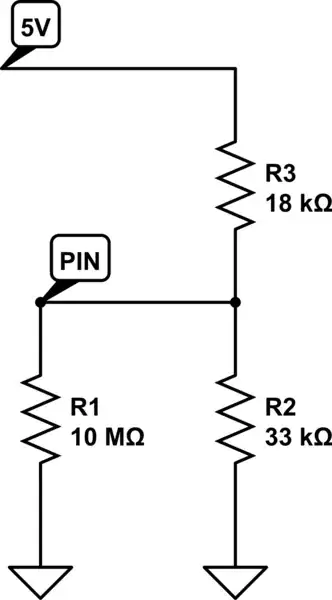
- Instead of using a capacitor to set the fault period, would it be possible to pull the TIMER pin low (see image below) to prevent the chip from timing out when in current limiting mode?

- If so, would it be safe for the main MOSFET Q1? I assume it could be selected to handle the maximum allowed current over a long period of time?
- If not, is there an easy alternative to get the intended behavior, or would I need to design a dedicated circuit for it (e.g. something like these (Wikipedia), or as seen many times on this forum)?
Thanks in advance!
