Here is an example:

simulate this circuit – Schematic created using CircuitLab
I have added a couple more components.
Here is how they all work together:
- The varicap diode changes its capacitance as the reverse voltage across it changes - higher voltage increases the non-conducting or insulating zone between the P and N type region, which is akin to increasing gap between plates of a capacitor, which decreases the capacitance between the P and N type region. The opposite happens as that voltage is decreased.
- In order to keep the varicap DC biasing voltage separated from the rest of the circuit, a capacitor whose capacitance is much larger than the largest capacitance of the varicap is used, so that it doesn't reduce varicap's effective capacitance significantly.
FM trim caps and varicaps are typically around 10-30pF, so 1nF DC blocking cap is plenty.
- R2 forms a very high impedance to the high oscillating frequency so that the tuning circuit is mostly unaffected by the components and voltages on the other side of it. R2 and C2 also form an RC low-pass filter which grounds the oscillations and keeps them from going to the rest of the circuit. They should be very close to the tuning circuit and all leads kept as short as possible.
- R1 changes voltage across varicap and thus its capacitance, therefore it's a tuning potentiometer.
- Some varicaps need as much as 30V voltage range to give their full range of capacitance values. If your tuning range is limited with a varicap, that could be the reason. You also need to get a varicap which has the range of capacitances you need for the range of voltages you have (check its datasheet).
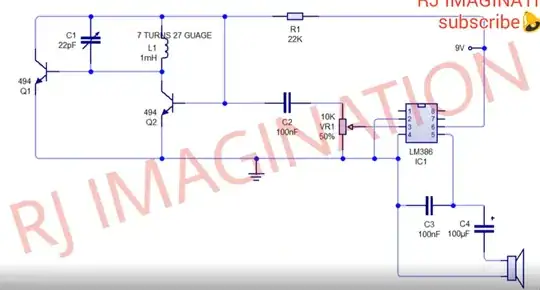
EDIT: Looking more carefully at your circuit, it has a 22kΩ resistor which will cause a significant voltage drop AND it will have high frequency component of the tuning circuit. That's why I have added C3, R3 and C4 to provide V+ to the cathode of the varicap.
It is much simpler if one of the tuning cap's ends is connected directly to one of the supply voltage rails (V+ or 0V).

