First I would like to thank the authors of the two answers for their responsiveness and benevolence. They gave me valuable ideas that enriched my understanding of this phenomenon, which I want to share with you in my answer.
As usual, I have accompanied my step-by-step explanations with CircuitLab simulations. In order not to clutter schematics with measuring devices, I completely rely on the attractive DC live simulation. For this purpose, just hover the mouse over the circuit and see the local voltages and currents.
These are "man-controlled" experiments where you adjust some parameter to get the desired value of the current (this is the best way to understand the phenomenon). To do this, open CircuitLab parameters window and start changing the quantity magnitude by observing the current through a DC live simulation.
Because these are conceptual schematics, where possible I have used convenient decimal values of the quantities - 1 or 10 [V, mA, kohm]. This simplifies the calculations since [mA].[kohm] = [V].
Similarity to a voltage source
The new insight for me was that these three current source configurations are analogous to the three voltage source configurations obtained by choosing a different reference point.
Floating sources
Both voltage and current sources are two-terminal devices and, in the general case, we see (work with) both ends of them. Thus, a voltage source has a positive and negative terminal, and as they say, the load will "see" both positive and negative voltage.
simulate this circuit – Schematic created using CircuitLab
Similarly, a current source has an
output and input terminal, and the load "sees" both.
simulate this circuit
A clarification: Since CircuitLab needs a ground, I have split the RL load into two parts (RL1 and RL2) and grounded the middle point.
Grounded negative terminal
However, we prefer to use only one terminal and connect the other to a reference point (e.g., "ground"). In most cases (e.g. in cars) we prefer to ground the negative terminal and then we get a positive voltage. Figuratively speaking, the load "sees" a positive voltage V+.
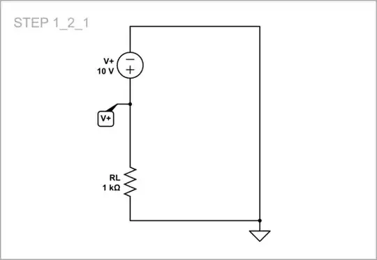
simulate this circuit
Similarly, if we ground the input terminal of a current source, the load will "see" its output terminal and will consider this device actually as a "source".
simulate this circuit
Grounded positive terminal
In some cases, we ground the positive terminal and thus we get a negative voltage (the load "sees" V-).
simulate this circuit
In the same way, we can ground the output terminal of the current source so the load "sees" its input terminal and will consider this device actually as a "sink".
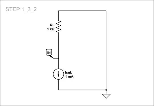
simulate this circuit
What is in the middle?
In the second part of my answer, I will consider the arrangement of interest where a floating current source is stretched through two resistors (RL1 and RL2) between the supply rails.
Ideal current source?
Let's first put an "ideal" current source from the CircuitLab library in this place.
simulate this circuit
The problem is that we do not know what is inside that circle with an arrow - is it a "true" current source that "produces" the current or an element that only keeps the current constant.
A source indeed
We can check it very easily by replacing the voltage source with a piece of wire. As we can see, the current continues flowing and the voltage across it reverses its polarity. So, we conclude, the CircuitLab current source is a true current source that contains energy inside.
simulate this circuit
Implementations
But in reality this is not always (more precisely, almost never) the case. Let's see what are these possible things that can be put in the circle with the arrow.
The schematics below are conceptual; their purpose is to show the basic idea. But I have mentioned the possible specific implementations (see also my answer about how to create current sources with "static" but colorful schematics).
Dynamic resistor
The most popular thing to put in the circle is a "varying resistor" which has the property of changing its resistance so as to keep the current constant. To imitate it, open Rvar parameters and begin changing the resistance so that to obtain the desired 1 mA current.
If now I come and try, for example, to increase RL1 or RL2, you will feel this and decrease Rvar accordingly so that the total resistance RL1 + Rvar + RL2 remains unchanged and hence the current.
simulate this circuit
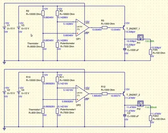
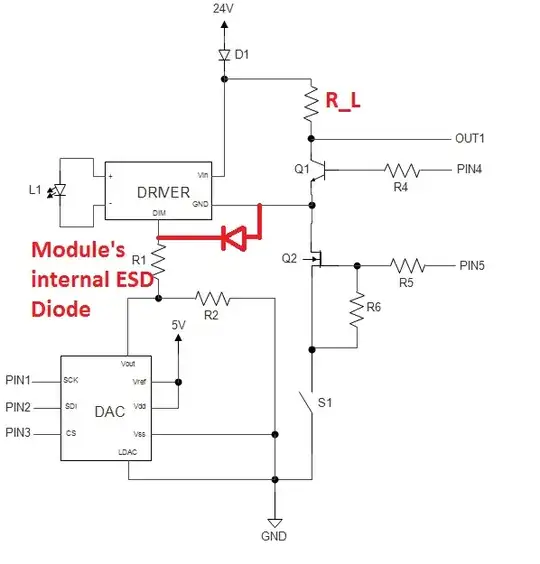
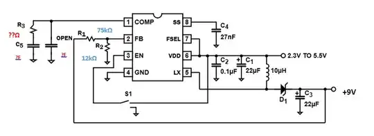
In real circuits, a transistor with constant base-emitter voltage does this boring work (see the schematic at the end of the question body). Also the so-called "constant-current diodes" made with JFET are a typical example ("diode" in the sense of a 2-terminal device, not PN junction).
Note that this is not a source in the literal sense of the word ("producing" current); it is a current regulating device. The current is produced by the voltage source V. The dynamic resistor is a passive device; so the voltage of its upper end is positive. As we saw above, the CircuitLab current source is not that.
Constant voltage source and dynamic resistor...
If we want to make a "true" current source, we need to include a constant voltage source in series with the dynamic resistor. Or, if you prefer, we need to move the external voltage source V inside the circle.
simulate this circuit
Note that now the "curcle" is an active device (in the sense producung power); so the voltage of its lower end is positive.
... dusturbed by resistance...
If I now come and insert a 1 k disturbing resistor Rdist, you will sense this and reduce Rvar to 7 k as above so that the total resistance remains unchanged (10k).
simulate this circuit
... or voltage
If I insert a disturbing 1 V voltage Vdist, you will sense this and increase Rvar up to 9 k so that the total current of 1 mA remains unchanged. And v.v., if I reverse Vdist, you will decrease Rvar to 7 k.
simulate this circuit
Dynamic voltage source and constant resistor...
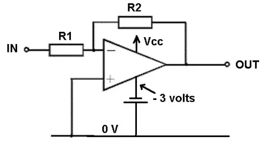
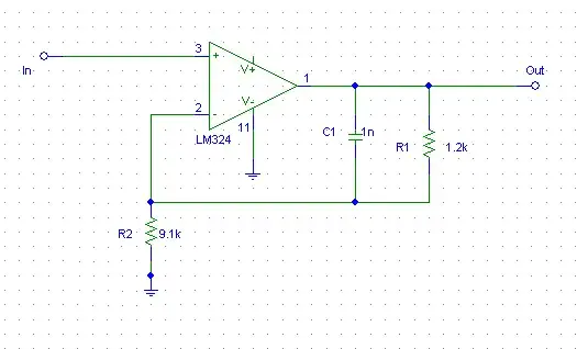
We can swap the role of the voltage source and the resistor making V varying and R constant. For example, the op-amp inverting current source acts this way.
simulate this circuit
... disturbed by resistance...
Now if I insert 1 k disturbance, you will increase V to 11 V to compensate the disturbance and keep 1 mA current.
simulate this circuit
... or voltage
If I insert 1 V disturbance, you will decrease V to 9 V to keep 1 mA current.
simulate this circuit
What should we call it?
Let's finally discuss the names extracted from the answers... although this is the least important issue:
Current source, current sink, floating current source
Current source, current sink, current source and sink
High side, low side and middle (floating) current source
Pinned to Vcc, pinned to ground, floating current source
There is some taftology because once "current source" is a generic name and then it is used as a specific name. Example: Current sources are divided into current sources and current sinks.