3

I'd like to make a LED strobe light for a turntable instead of the old glimm light. I've seen some solutions for it by using a crystal oscillator + divider to achieve 100 Hz (I'm in in the EU with 50 Hz 230 V), but I don't have any blueprints to reproduce it. The turntable's power supply has a 10 V AC and 18 V AC outputs to use.

What kind of oscillator and divider do I need to make this and what other parts? Does the voltage to the oscillator need to be stabilized?

An example of someone's solution

Further clarification: I want to be able to set the speed of the record accurately with the dots on the side of the platter. If the marks are "frozen" then it's set correctly.

Peter Mortensen
  • 1,676
  • 3
  • 17
  • 23
  • Hello and welcome. Are you trying to make the 100 Hz strobe to check the speed of the record turntable? The 10 V is AC as well? Can I ask what's a "glimm light"? – jonathanjo Apr 24 '23 at 19:20
  • 2
    On the side of a turntable, you have dots, that interact with a flickering/strobing light. It gives you a good visual look at how fast the turntable is moving. I think that's what he's trying to recreate. – LordTeddy Apr 24 '23 at 19:31
  • 3
    We don't use blueprints in EE. – Andy aka Apr 24 '23 at 19:32
  • 1
    @LordTeddy indeed ... but I was wondering what a glimm light is – jonathanjo Apr 24 '23 at 19:51
  • 7
    Neon bulbs are called *Glimmlampe* in German. – Janka Apr 24 '23 at 20:50
  • 3
    Yeah, and fluorescent lights are called "neonröhren" despite there not being any neon in them. Languages are strange things. – JRE Apr 25 '23 at 09:11
  • Hello. Yes, I'd like to make a 100 Hz strobe with LED to be able to set the speed of the record accurately with the dots on the side of the platter. If the marks are "frozen" then it's set correctly. The 10 V is AC as well. The glimm is answered, yeah it's called neon bulb too, sorry for the confusion. – driverhertz Apr 25 '23 at 10:05
  • (Thanks for clarifications!) Is your turntable motor AC, do you know? – jonathanjo Apr 25 '23 at 10:17
  • The motor is DC regulated. – driverhertz Apr 25 '23 at 10:27
  • This could be the very definition of an XY problem - asking for implementation Y when you need to solve X. Any Arduino and 8 lines of code would solve this for you with the added benefit of sharper on-off behavior. You could even let the Arduino determine the speed directly for you. – winny Apr 25 '23 at 10:52
  • 3
    @Andyaka Notice that blueprint used to mean the printing process (which makes blue prints, and was used in all disciplines, but nobody uses it any more) and now refers to a plan of something. Both meanings can apply to electronics. – user253751 Apr 25 '23 at 13:33

3 Answers3

10

Honestly, the analogue way with diodes and using the AC frequency is a much better way to do this. The digital way here is just to explain the original example given in the question, or if you want crystal accuracy, or just avoid the potential 4% variation in short-term AC frequency.

The example you gave is a small microcontroller circuit. You could achieve it with almost any microcontroller, such as any of the small Arduino family. If it has a crystal (basically all do) you will be as accurate as the one in your example.

The first program anyone runs on such a thing is something to blink an LED, and it's very easy. There are innumerable "blink LED" tutorials available.

It is much easier to get your code onto an Arduino board than a bare microcontroller. For best accuracy, you could program the in assembler or C, but the Arduino coding environment is certainly the easiest way to get yourself going. It all depends on what's easiest for you.

It's entirely possible to do this with a bare microcontroller such as the ATTiny of your linked example, with its internal oscillator or an external one, but you're doing perhaps a lot of work if it's new to you. An external crystal oscillator might go at 8 MHz and have an accuracy around 50 ppm. You can use a module (simplest) or a crystal and two capacitors (cheaper). There is an internal oscillator you could use instead, but it must be calibrated and is generally regarded as about 1% once youv'e done that; if that's good enough you can do without the crystal and just use a CPU such as the ATTiny85.

From your 10 V supply you need to produce 5VDC or 3.3VDC (depending on your chosen microcontroller). You'll want to keep all this as far away from your analogue audio signals.

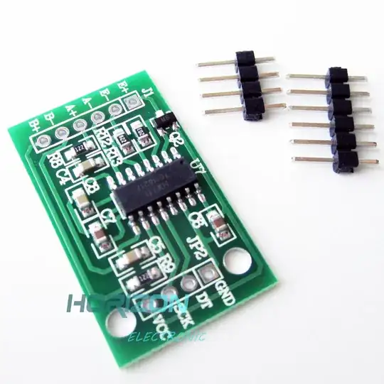
A blueprint of the microcontroller circuit might be like this: enter image description here
jonathanjo
  • 12,049
  • 3
  • 27
  • 60
  • 4
    What did you use to make a blueprint out of the schematic diagram? – JRE Apr 25 '23 at 09:13
  • 9
    @JRE KiCAD / "Plot to PDF in black and white" / Screen grab / GIMP / Invert, black to transparent / Find "blueprint background image" / Paste. I was having a playful moment, with apologies to Anda AKA. The first place I worked actually did have circuit diagrams as blueprints. – jonathanjo Apr 25 '23 at 10:01
  • 2
    I love it. Personally I'd have moved X1 to the right and flipped it over vertical axis (so out 8 can be aligned with xtal1), makes the image even clearer, but the background is a nice feature of the bluep.. eh, schematic. – Mast Apr 25 '23 at 10:49
  • 1
    @mast thanks for compliment. Those who taught me were obsessed about signal flow going from left to right if at all possible and were happy enough with longer lines, so long as things were clear, and their voices are loud in my head to this day. – jonathanjo Apr 25 '23 at 11:00
  • 1
    This is why we don't use blueprints any more. – Andy aka Apr 25 '23 at 13:36
  • 1
    @Andyaka yes, print quality was awful, very frequently contact wasn't kept so text was fuzzy to the point of unreadable. It's a lovely shade of blue though. Best wishes, apologies for a little fun. – jonathanjo Apr 25 '23 at 14:05
  • Beautiful. I can almost smell the ammonia. – Spehro Pefhany Apr 25 '23 at 23:49
5

Your turntable has 18V AC available. That allows for a very simple circuit:

schematic

simulate this circuit – Schematic created using CircuitLab

Adjust R1 to control the brightness. Adjust the number of series diodes D1, D2, D3 to control the contrast. If the contrast is too weak, use a zener in the opposite direction instead. You can build the bridge rectifier BR1 from 1N4148 diodes as well as the LED current is only about 20mA.

Janka
  • 13,636
  • 1
  • 19
  • 33
  • 2
    Using the mains as a frequency reference has the disadvantage that it can vary from 49.8–50.2 Hz in normal operation ([in the UK](http://mainsfrequency.uk/fm-home)). – Andrew Morton Apr 25 '23 at 08:35
  • 4
    @AndrewMorton Does that variation not affect the regular glimm light too? – QWasson Apr 25 '23 at 08:47
  • 2
    @QWasson Yes, that's the reason for using a crystal oscillator instead. – Andrew Morton Apr 25 '23 at 11:02
  • anyway, doesn't it make sense to sync the turntable speed to the AC frequency so that it stays in sync when the motor frequency also changes due to the AC frequency? – user253751 Apr 25 '23 at 13:36
  • 3
    @user253751 The goal is to be able to adjust the turntable to constant speed, so the pitch of records played remains constant, regardless of what the mains AC rate is doing. – Russell Borogove Apr 25 '23 at 14:24
  • @RussellBorogove then why do they use neon lamps? – user253751 Apr 25 '23 at 19:04
  • @user253751 They are cheap and give a fair approximation to the correct speed most of the time. Maybe don't adjust your turntable speed just at the start of an advert break in a significant episode of Coronation Street ;) – Andrew Morton Apr 25 '23 at 19:27
  • 1
    @user253751 The AC rate isn't the only variable; with an AC-powered neon lamp you can at least trim out drift in the motor control circuit and varying amounts of friction in the mechanical portion – Russell Borogove Apr 25 '23 at 20:14
  • @Andrew Morton: It's not possible to adjust the motor speed that precisely. The turntable speed will creep regardless how good your measurement timebase is. – Janka Apr 25 '23 at 20:38
  • @Janka Yes, but if your measurement timebase could be off by up to 1% (mains), isn't it better to have a measurement timebase that could be off by 0.01% (say, for a crystal)? At least you'd be sure of starting from somewhere guaranteed to be closer to the correct value. – Andrew Morton Apr 25 '23 at 22:08
0

The circuits you've seen probably use a fairly stable oscillator like a crystal (RC/555s are out) and a divide by N counter like a 4521 to bring the frequency down to 100 Hz or whatever you need. There's a schematic of a crystal setup on page 5 of this datasheet, but I would suggest a self-contained oscillator chip to save yourself the layout headaches. You will need an output buffer (BJT, MOSFET, etc) if the source current is low.

vir
  • 14,718
  • 13
  • 28