7

I have been trying to work out a circuit something like the following:

schematic

simulate this circuit – Schematic created using CircuitLab

I want VOUT to be 3V when the switch is open and 5V when the switch is closed. The simulation seems to give me what I want when the switch is open, but not when it's closed. What am I doing wrong? Is there a better way to do this? I was avoiding a common cathode diode pair to avoid the forward voltage drop.

vicatcu
  • 22,499
  • 13
  • 79
  • 155
  • Are you limited in the switch you are using? a single pole dual throw switch would easily swap between the two supplies – Gorloth Apr 21 '13 at 05:28
  • @Gorloth... the switch exists for the purposes of simulation only. It's meant to simulate the attaching and detatching of 5V power from the circuit. I don't want a mechanical switch ultimately. – vicatcu Apr 21 '13 at 05:40
  • what exactly is it doing when the switch is closed? what's the voltage at vout? – Gorloth Apr 21 '13 at 05:50
  • @Gorloth when the switch is closed VOUT should be 5V, when the switch is open VOUT should be 3V. – vicatcu Apr 21 '13 at 07:04
  • YOu say the desired behaviour of 3v or 5v at vout, but you also say when simulated it does not work when the switch is closed, but you specify how it's not working, if you are getting a vout that is ~3.6v then sounds liek a body diode issue that Brian mentions in his answer below – Gorloth Apr 21 '13 at 19:06

2 Answers2

3

I came up with the following circuit that does what you ask:

Rail Switcher

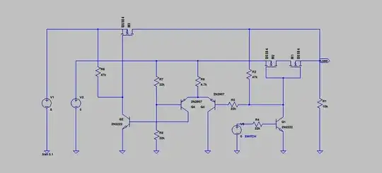
5 volts from the "SWITCH" source will turn on M1 and M2, connecting the 3 volt rail to the load, and pulling current out of the right hand transistor of the differential pair Q3 and Q4. This turns off Q2 and shuts down the 5 volt rail. When Q1 turns off by applying 0 volts to "SWITCH", Q4 is biased on by the voltage divider comprised of R7 and R8, which turns on Q2 and the 5 volt rail. R2 then pulls up the gates of M2 and M1, shutting the 3 volt rail off. The arrangement of M1 and M2 prevents conduction from the 5 volt rail into the 3 volt rail when the 5 volt rail is connected.

In a real circuit there should probably be stopper resistors on the MOSFET gates.

Another way, in response to the "too many components" criticism:

comparator switch

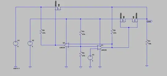
If you don't want to use discretes, you can do it with a cross-coupled dual comparator. One IC and 4 resistors, plus the switches.

MattyZ
  • 2,926
  • 1
  • 22
  • 23
1

Measure currents around the 3V MOSFET M2 when the switch is closed. I have a feeling that 5V on its drain is forward biassing the body diode and limiting VOUT to 3.6V (or some value dictated by M6's ON resistance. You may need a pair of MOSFETs there, in series, (usually with their sources connected together) to provide isolation in both directions.

(Edit: add schematic) Remember this is speculation, I haven't tested it : but the basic idea is this

schematic

simulate this circuit – Schematic created using CircuitLab

When on, (SW4 open) both transistors M2,M7 conduct.

When off, both transistors are off; their body diodes conduct in opposite directions, so neither conducts.

But I would welcome correction or improvements to the design