1

I'm trying to drive a 12-24 V DC motor with MCU PWM output. My design is based on a totem pole gate driver

First I use a voltage divider to provide the full-on gate voltage (10 V) for my power MOSFET.

Schematic:

enter image description here

I use R3 and Q4 to turn off both totem pole transistors. The DC motor is simulated with DC power. Switch S1 is used for MCU startup situations to not run the motor at startup.

I ran the simulation in Multisim and it shows the MOSFET never turns off and the current in PWM mode is lower than I am expected.

What part of this design is missing? Can a simpler design be made that is robust for different DC motor voltages?

The circuit was made in online Multisim and is available through this link.

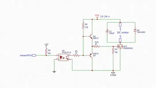
new circuit using an optocoupler to isolate the powers

enter image description here

updated circuit

enter image description here

Hamid s k
  • 195
  • 1
  • 9
  • 1
    The schematic symbol for the IRF450 looks like P-channel device, but it is NMOS. A PMOS device would conduct through its D-S diode. – PStechPaul Apr 16 '23 at 23:34
  • yes, the symbol is wrong , however I only need to use n mosfet – Hamid s k Apr 17 '23 at 00:10
  • (That symbol is N-MOS enhancement mode - *no bulk*, whatever this means outside an integrated circuit.) – greybeard Apr 22 '23 at 08:27
  • FYI, at least the way Texas Instruments uses the terms, your driver is a push-pull, not a totem pole. A totem pole driver has two transistors of the same type (e.g. both NPN) and both oriented in the same way. Push-pull drivers have complementary transistors configured as complementary emitter (source) followers. – Math Keeps Me Busy Apr 22 '23 at 13:15
  • @math-keeps-me-busy can use a totem pole as well as a push-pull circuit to derive the N-Mosfet efficiently – Hamid s k Apr 22 '23 at 21:02
  • Just make sure the MOSFET can withstand 24 volts on the gate - otherwise, add a voltage regulator or zener diode. And you will need to add some capacitors on the power supply. – PStechPaul Apr 22 '23 at 22:29
  • 1
    24 V exceeds Q13's \$V_{GS}max\$ of 20 V. C1 is misplaced. – greybeard Apr 22 '23 at 22:53
  • @greybeard I will parallel the 10v Zener to R1, How come electrolytic capacitor C1 misplaced?! – Hamid s k Apr 23 '23 at 13:12
  • `will parallel a 10 V Zener to R1` shift it to *bases to COM*. Buffering (C1 + foil/ceramic capacitor) should be from \$V_{load}\$ to COM; see [Edin Fifić's answer](https://electronics.stackexchange.com/a/663111/274544) for a suggestion for a snubber. (One more bypass capacitor would be in order between the collectors if there wouldn't be clipping to about 10 V.) – greybeard Apr 23 '23 at 13:34

1 Answers1

6

Your schematic is a copy of another schematic and you have added some unnecessary parts while missing at least one.

  1. Your node 4 was and should have stayed connected directly to 12V (node 9), without the R5/R6 voltage divider. 12V is fine for driving a MOSFET, especially since it drops by about 0.6V through the Q2 transistor.
  2. R2 resistance is too large; it should be no more than 100Ω.
  3. If the switch S1 condition is OFF in the simulation, that will keep the MOSFET on.
  4. R1 should be 47Ω-100Ω.
  5. DC motor should added between the 24V battery and MOSFET, or at least a resistor simulating the impedance of the motor.
  6. The motor will need an RC snubber or a diode across it to protect the MOSFET from its inductive kickback.
  7. The Multisim MOSFET model could be wrong.
  8. You need a capacitor across the 24V power supply rails.

EDIT: Based on your question below, I realize I have forgotten your main issue, that is the MOSFET staying on without a signal being applied (switch S1 open). Below is the schematic section relevant to your problem:

schematic

simulate this circuit – Schematic created using CircuitLab

  • I have kept transistor and resistor numbering the same as in your schematic to make it easier for you to follow the changes.
  • R5 keeps the Q4 on when the switch S1 is off. This keeps the totem pole output low and the MOSFET off.
  • Q4 itself prevents the voltage on its base going over 1V, protecting the square wave generator.
  • R1 limits the current into the transistor to below 20mA. If the 1 kHz generator can supply higher currents, you can reduce R1 value to 100Ω.
  • The totem pole output keeps the MOSFET off when switch is off, but I have added (left in place) the R4 just to make sure it stays off if 12V is off.
  • RC snubber (R6 and C1) reduces EMI.
  • Diode D1 prevents inductive kickback from destroying the MOSFET.
  • L1 represents the DC motor coil(s).
Edin Fifić
  • 5,188
  • 7
  • 24
  • I add the voltage divider so it could be adjusted for different voltages and Mosfet. how can turn the MOSFET off when switch S1 is off? – Hamid s k Apr 18 '23 at 21:35
  • @Hamidsk You could add another transistor between Q4 and the totem pole pair Q2 and Q3. I will update my answer with a schematic. If you find it answering your question, you should mark it as accepted answer. – Edin Fifić Apr 18 '23 at 21:42
  • 1
    @Hamidsk I have made a schematic which is simpler and is fully functional. The problem of the MOSFET staying on is solved with a resistor keeping the Q4 on. Check my answer and the schematic. If it is acceptable, you should accept it as your answer. – Edin Fifić Apr 18 '23 at 23:05
  • tnx @edin-Fifić, if I want to have same power for the motor and driver, should I only change R3? do V4 and L1 equivalent of dc motor or also include R6 & C1? – Hamid s k Apr 21 '23 at 00:15
  • 1
    @Hamidsk Sorry, I forgot to mention L1 is the motor coil(s). It's corrected now. I don't understand what do you mean by "same power for the motor and driver". – Edin Fifić Apr 21 '23 at 00:54
  • I think that means using just the 24 V supply. Best way might be a 7812 regulator to get 12V from 24 V. – PStechPaul Apr 21 '23 at 01:29
  • Any particular reason why R1 is so small? A typical digital output might struggle with anything under 500Ω or so. Under 1kΩ would be an abuse of a Raspberry Pi GPIO output. It also saturates Q4 so hard, it takes ages to recover. – Simon Fitch Apr 21 '23 at 02:09
  • @PStechPaul Thank you. I've had a bad cold for 3 weeks, been exhausted and dehydrated, and it's been messing with my ability to think/comprehend. Plus, Hamid wasn't clear in his question. 7812 is one of the ways to do it, yes. 7810 would be even better a bit. – Edin Fifić Apr 21 '23 at 08:15
  • @SimonFitch I used the smallest resistance safe for an Arduino output to ensure faster turn off of the MOSFET. If the questioner has mentioned the type of the square wave signal source, I have missed it. Also, because the PWM frequency is so low (1kHz), slow recovery shouldn't be a problem AFAIK. – Edin Fifić Apr 21 '23 at 08:20
  • @edin-Fifić base on your design I add the new circuit to isolate the Mosfet from the Arduino PWM pin, do I need R3? does this schematic work – Hamid s k Apr 22 '23 at 07:17
  • 1
    @Hamidsk As far as I know, you don't need R3. Also, R4 as a pull-up is unnecessary, but you should put it in series between Arduino and optocoupler input AND reduce it to about 330Ω to 1kΩ.. If you want your PWM phase to be the same at the input and the output, you should connect optocoupler LED anode to +5V and its cathode to Arduino output. The schematic should work. – Edin Fifić Apr 22 '23 at 18:39
  • @edin-Fifić I update the circuit. with this schematic will the DC motor remain off on MCU start up – Hamid s k Apr 22 '23 at 21:00
  • 1
    No. If the opto-isolator is not driven low, R2 will bias the totem pole gate driver high, and the motor will be ON. You could move the opto-isolator to where R2 is, and move it to pull the base drive low in the absence of drive signal. – PStechPaul Apr 22 '23 at 22:33
  • @PStechPaul You're right, my bad. My mind is still fuzzy coming out from the cold, I couldn't pay attention to everything. He was right from the start with the placement, BUT the 10KΩ resistor would give him a current of about 0.4mA, and optocouplers don't amplify much. He would need at the most a 1kΩ resistor to ensure the MOSFET turn-off during no PWM signal. It complicates things. – Edin Fifić Apr 23 '23 at 00:01
  • 2
    @Hamidsk See my reply above to PStechPaul. Adding an optocoupler complicates things and doesn't work as well as with a plain transistor. Do you really need an optocoupler? Also, please stop updating circuits and questions, you are asking for engineering hours to be spent, and there is a reason those hours are expensive. You had a problem and a question, and they were addressed and solved. Continuing with more requests through a single question is unrewarding and against the rules. Any more questions or problems, post them as new questions, please! I could be answering other questions instead. – Edin Fifić Apr 23 '23 at 00:05