1

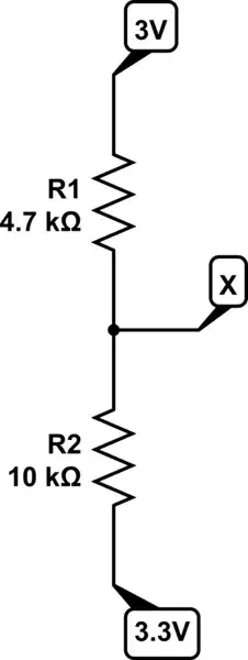
I have two PCB that i have to interconect. In the first one it is R1 (pull-up resistor) in the second one is R2 (pull-up). The yellow rectangle represents the interface between boards. My questions are:

  1. Which would be the value of the parallel resistors with different Vcc? In theory you cannot connect voltage sources with different values in parallel so I don't know how to calculate both the parallel resistor value and the equivalent-parallel voltage value.
  2. The maximum GPIO voltage of the first (left) board (for the microprocessor) is 3V, would this configuration connecting to other pull up to +3.3V break the microprocessor? enter image description here
  • 1
    There is some important information missing: - How the GPIOS are configured? output or inputs? Are they bi-directional? or three-state GPIOs? Regarding your question 1: If both pins are input, the voltage will be over 3V: VL = 3V + (3.3V - 3V) . 4.7K / (4.7K + 10K) = 3.1 V Regarding your question 2: I would not do it. Take a look to this: https://electronics.stackexchange.com/questions/82104/single-transistor-level-up-shifter – MF3 Apr 11 '23 at 13:02
  • @MF3 the pins are used of I2C communication so they are inputs and outputs (?) – Developing Electronics Apr 12 '23 at 05:24

2 Answers2

2
  1. They are not in parallel since the top ends are connected to different nodes (sources). So we can't say any parallel equivalent here.
  2. It may or may not. Assuming the GPIOs are configured as open drain, the bus voltage (when the bus is at idle i.e. both nodes "released" the bus by turning off the bus switching transistors) will be determined by the voltage divider equation:

schematic

simulate this circuit – Schematic created using CircuitLab

$$ \mathrm{\frac{3.3-V_X}{10k}=\frac{V_X-3V}{4k7} \\ \Rightarrow V_X=3.1V } $$

would this configuration connecting to other pull up to +3.3V break the microprocessor?

The bus voltage, at idle, stays at 3.1V. Since you didn't give any info about the MCU (model number and datasheet), it's difficult to answer but generally, the maximum voltage for a GPIO pin is limited to something between VDD+0.3 and VDD+0.6V, depending on the particular family and design. So if your MCU is supplied with 3V then 3.1V will be within the absolute maximum ratings. But still it's not recommended.

Rohat Kılıç
  • 26,954
  • 3
  • 25
  • 67
  • The MCU has 3.3V power supply but it is specified that the pins can handle only 3V with maximum rating to 3.15V so 3.1V is too near to the limit to be safe. Thanks. – Developing Electronics Apr 12 '23 at 05:20
1

You have 10k pulling up to 3.3V and 4k7 pulling that down to 3.0V. If you round the numbers you end up seeing that the voltage is pulled twice as strong to 3.0V than 3.3V so resulting voltage is approximately 3.1V. And resulting impedance is about 3.2 kohms.

Pulling voltage higher to 3.1V might or might not be within limits of the MCU powered by 3.0V. It depends which MCU it is, how the IO pin is configured (pushpull, opendrain), and if the IO pin is tolerant to voltages outside the supply voltages.

Usually 0.1V difference is not much, but if the 3.0V MCU will be unpowered, there will be leakage current via the 3.3V pull-up to MCU IO pin and to 3.0V supply, which may be what you don't want.

Justme
  • 127,425
  • 3
  • 97
  • 261
  • How do you calculate the resulting impedance? You did a regular parallel calculation while this is not a regular parallel resistor configuration due to the power supplies. Is that correct? Which value is enoght for pull-up or pull-down resistors? – Developing Electronics Apr 12 '23 at 05:21
  • Which configuration (push-pull or opendrain) can handle better voltage variations out of the range? – Developing Electronics Apr 12 '23 at 05:22
  • It is a voltage divider. You simply have 0.3V over 14.7 kohm so rest is known. You have both resistors affecting the same node so equivalent impedance and voltage is known. And definitely opendrain if you have control over it. But why do you ask, you alreay chose a correct answer? Also your next problem is, which one is better; pull-up to 3.0V might not be good for 3.3V input and 3.3V might not be good for 3.0V output. You need something there. – Justme Apr 12 '23 at 05:30