The basic approach is simple: throw a 48V voltage source between the battery and the output:
simulate this circuit – Schematic created using CircuitLab
Of course, the problem is then: "how do we get an accurate voltage source like that?".
We could use an ATL431LI shunt reference, since it can operate on a meager 80μA:
simulate this circuit
That one is very accurate and works down to about 48.01V.
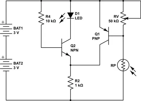
One other approach uses a resistor loaded with a current source as a voltage offset generator that is then buffered:

simulate this circuit
Adjust R1 for 5.000V on the voltmeter when the battery is at mid-voltage, ie. 53V. You'd want to use an adjustable power supply for that purpose.
RV models the voltmeter's input resistance. It can be pretty much anything, without introducing much error, thanks to the mosfet output buffer.
A mosfet's threshold voltage drops with temperature - in the very rough ballpark of 6mV/K per mosfet. That's not a big deal for such battery monitoring, most likely.
I1 needs to be stable with temperature. It would be lovely to use an LM334, but that won't work, as it's a PTAT current source - proportional to absolute temperature - and the tempco at the gate of M1 would be about -0.1V/K. That'd be quite bad.
Instead, we need something much more stable. REF200 would do the job, resulting in a tempco of about ±1mV/K. That's better than the buffer stage.
M2 provides additional voltage drop to keep M1's gate voltage within I1's compliance range, i.e. at minimum 2.5V.
R3 provides short-circuit protection on the output, and dissipates 0.06W when the output is shorted.


