26

It is known that a BJT transistor looks like two diodes back to back (or head to head). With this in mind, theoretically we should be able to build a full bridge rectifier with 2 BJT transistors, one PNP and the other NPN, with the emitters connected together and the collectors connected together - the two bases being the other two terminals.

Is there any reason why this should not work?

I do not claim that this should be attempted instead of a proper solution, I am just trying to verify my thinking.

virolino
  • 439
  • 3
  • 11
  • 1
    "a BJT transistor looks like two diodes back to back" and yet it doesn't work like two diodes back to back, because that's not really what it is. It's a misleading oversimplification. It's an NPN junction with varying doping levels and sizes, that's what gives it it's properties, and those properties are not appropriate for this – Shredder Apr 08 '23 at 04:08
  • 1
    Why don't you hook it up and see how it works;? That is more scientific than relying on "experts". – richard1941 Apr 16 '23 at 14:51
  • 1
    @richard1941: Because I simply do not have any of the materials and any of the tools needed for the experiment. And investing in the proper tools just to find an answer which is readily known by actual specialists, is just too expensive and too irrational. – virolino Apr 17 '23 at 06:25

5 Answers5

30

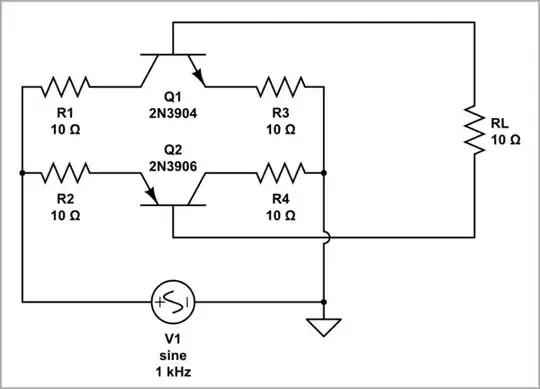
That would be something like this...

BJT FWB equivalent circuit

This is kind of a one-line proof, or proof by diagram; if you understand BJT operation.

tl;dr

It's not useful. Using common transistors, the transistor effect (collector current in response to base current) effectively shorts it out; for every mA of DC load current, ~200mA is sunk across the AC source. The voltage limit is also quite low (VEBO, about 7V), as is the current limit (base current is typically a fraction of collector current).

In Detail

when the B-E junction is forward biased and B-C is reverse, current "bleeds through" from E to C, crossing the base layer without being discharged through the pin. A BJT is not simply two diodes glued together, but magic happens when they are glued together very very closely (but not actually glued together; indeed the base layer needs to be of the same crystal).

I myself remember wondering why, ever so many years ago, I couldn't simply slap two diodes together and make a transistor. Well, in a sense, it does, it's just that the hFE is pretty damned close to zero. We have the inverse problem here, that hFE is too high to make practical diode pairs with BJTs.

For typical BJTs with hFE ~ 100, indeed the collector current utterly dominates, and the AC source is simply shorted out (when its voltage is above two diode drops, anyway, and load current is being drawn).

Can we make it work at all?

There are cases in integrated circuits, where the hFE might be made quite small (but not zero); in that case, it could work as a normal bridge rectifier without much trouble. Maybe that could be worth tolerating the "leakage" (read: collector current), for, I don't know, signal rectification or something? But that's a very specialized field, IC design I mean, and this is very much reaching for any kind of application to explain this circuit. And anyway, I don't think there's any case where just single diodes wouldn't be easier (or diode-strapped BJTs, as the case may be).

Component limitations apply, of course; base current limits are typically low (a modest fraction of the collector current rating), and E-B voltage limit is rarely more than 7V and I don't think I've ever seen one over 30V*. Fusing ratings are absent (likely limited by base current), so they would not be very robust as power rectifiers, even without the hFE problem.

*There are SiC BJTs (they call them SJTs for some reason..) available nowadays, with ratings up to 25 or 30V. Antique germanium BJTs were typically of these ratings as well (and often symmetrical, so VEBO = VCBO), though higher voltage parts were available, that I just haven't seen.

Not to beat the proverbial dead horse, mind -- it's fun to entertain ideas like this, and see exactly how and why they fail to do something, and in exactly which ways. While this idea happens to have several, very solid reasons striking it down, it does sometimes happen that a strange little circuit idea, while mostly useless, has just a couple narrow cases where it can be applied, indeed perhaps to great advantage!

Tim Williams
  • 22,874
  • 1
  • 20
  • 71
  • 1
    Your answer is as beautiful as the "whiskey speech" https://en.wikipedia.org/wiki/Noah_S._Sweat#The_%22whiskey_speech%22 :) Can you please somehow clarify if my crazy "invention" can work as a full bridge rectifier? Even if in very narrow conditions. I have the feeling that you somehow approve of it, but I cannot put my finger on it. – virolino Apr 07 '23 at 11:04
  • 2
    That *really* is a great answer to a simple-looking question. – jonathanjo Apr 07 '23 at 11:45
  • 1
    @virolino Ha, indeed! To be clear: no, it's not really useful. The furthest application I can think of would be in ICs, where diodes are sometimes made as BJTs; but even then, it would be better to use isolated ones, rather than using one BJT as a pair of diodes. – Tim Williams Apr 07 '23 at 12:26
  • 1
    @TimWilliams: so in an IC, they would build a BJT, but use only one of the junctions, you mean? – virolino Apr 07 '23 at 12:28
  • 3
    Sometimes -- or, slightly cleverer, tie B+C together ("diode strapped" BJT), which makes a somewhat more ideal diode. Depends on the application. They might even tie B+E together, to get higher breakdown voltage (since Vceo > Vcbo in most cases). – Tim Williams Apr 07 '23 at 12:31
  • 1
    @TimWilliams: so you say that "my" circuit would not work simply because the "transistor effect" would interfere too much with the "diodes effect" of the junctions? – virolino Apr 07 '23 at 12:31
  • 1
    @virolino Correct. – Tim Williams Apr 07 '23 at 12:33
  • 1
    @TimWilliams: now it's clear. Thank you for the answer and for the clarifications. – virolino Apr 07 '23 at 12:35
12

Nothing left to do but try it out:

schematic

simulate this circuit – Schematic created using CircuitLab

V1 sweeps between +/-10V. If you try it on real transistors, limit it to +/-5V and don't run them very long as things will get hot rather quickly.

Here are the collector and emitter currents of both transistors, as well as the load resistor current:

enter image description here

Notice how the load current is much smaller than the cross-conduction current, i.e. the current flowing between collector and emitter of these transistors, essentially shorting out the AC source.

The schematic can be drawn in another way:

schematic

simulate this circuit

V(Transistor as diodes)

The result should be explained somehow...

Here is the classic diode circuit for comparison:

schematic

simulate this circuit

The result of the DC sweep...

Full wave rectifier DC sweep

... and Time domain simulation.

Full wave rectifier Time domain

6

schematic

simulate this circuit – Schematic created using CircuitLab

The addition of these two resistors makes the circuit work to some extent, although getting about 4 mA output into 1k causes about 500 mA input current. Adjusting these values might make for slightly better performance, but it is still wholly impractical.

In fact, the resistors don't do very much, although the output does get rectified better than the circuit posted by @KubaHasntForgottenMonica

Voltages

Input current

Edit: I used a 2N2955 for Q2 and 2N3055 For Q1 (both have beta of 60), and with R2 and R3 220 ohms, and there is some improvement, where current is only about 100 mA. Maybe some really bad old transistors with very low current gain might be even better, but I doubt it will be practical.

Input and output voltages

Input current

PStechPaul
  • 7,195
  • 1
  • 7
  • 23
  • What do these resistors do? Maybe limit the reverse voltage across the base-emitter junctions? – Circuit fantasist Apr 08 '23 at 06:30
  • 3
    They don't do much. I just had an idea to try, and they seemed to help a little bit. Maybe they reduce the beta so they don't draw as much current. – PStechPaul Apr 08 '23 at 06:47
4

No it won't work, because a BJT is not simply two diodes back to back.

It only appears to look like two diodes back to back, under limited conditions, such as when probed with a multimeter in diode or resistance modes.

Justme
  • 127,425
  • 3
  • 97
  • 261
  • So you say that the two transistors connected as I explained will never ever rectify anything? Just like 2 diodes connected back to back will never amplify? I find that kind of hard to believe (as a simple hunch, not as science). Please note that my question is not about being practical, but just about being possible. I welcome any additional clarification. – virolino Apr 07 '23 at 10:58
  • Use FOUR transistors, and leave the emitters unconnected. That might work. – richard1941 Apr 16 '23 at 15:01
2

Is there any reason why this should not work?

A practical rectifier diode can survive a reverse voltage of hundreds or thousands of volts (device dependent). A reverse biased base-emitter junction might be reliable for 7 to 12 volts. Hence the application areas are very limited for using BJTs.

Andy aka
  • 434,556
  • 28
  • 351
  • 777