3

I have to build an MCU system that has to measure a dual voltage, V+ and V-. The problem is that my system needs to be powered with a single power supply.

To measure the V+ input, no problem, I simply make a resistive divider and an op amp as a buffer before the ADC: enter image description here

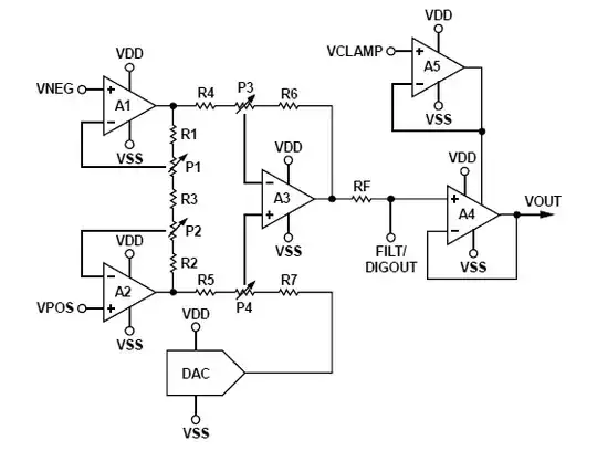
The problem arises when I have to measure the negative V-, looking on the internet I found this image: enter image description here
which I tried to apply to my situation like this: enter image description here
But the problem is that the measuring range of the negative voltage V- depends on the positive voltage V+.

Then I came up with another idea, since the op amp can also be powered in dual supply. I could take the circuit I use to measure the positive input V+, reverse the power supply to the opamp (the positive power pin to ground and the negative power pin to +VDD); so I would get an output between 0 and -VDD, which I could then bring back positive with the same circuit I found on the internet (an output divider): enter image description here
Can this be done? Could that be a better solution?

Last question: before the op amp I used a second TVS diode for overvoltage protection, but I doubt whether it is better to use a 3.3V zener, what do you think?
Federico Massimi
  • 735
  • 1
  • 10
  • You might consider using an IC that does this for you if that is acceptable in your design. TI/AD and others offer some that do negative voltage monitoring. Alternatively you could go for a solution using two voltage monitors as [described here](https://www.ti.com/lit/an/sbva062/sbva062.pdf?ts=1680781111872&ref_url=https%253A%252F%252Fwww.google.com%252F) – Mu3 Apr 06 '23 at 11:40
  • If you connect the positive power pin to gnd, you then need to connect the negative power pin to *a negative voltage*. Connecting V- to a higher voltage than V+ will just fry the chip. – Hearth Apr 06 '23 at 14:53
  • @Mu3 I've been looking for this type of chip, but at least what I've found, they only provide an indication of whether or not the voltage is in a certain range, but I should measure the voltage instead, I would need an analog output to send in an ADC (internal ADC of an MCU). – Federico Massimi Apr 06 '23 at 15:09

1 Answers1

3

Then I came up with another idea, since the op amp can also be powered in dual supply. I could take the circuit I use to measure the positive input V+, reverse the power supply to the opamp (the positive power pin to ground and the negative power pin to +VDD); so I would get an output between 0 and -VDD

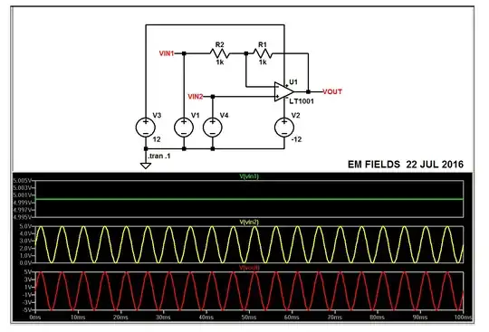
An op-amp will burn if you reverse the power pins. Forget that idea. Instead, for measuring the negative voltage, connect the op-amp as an inverting circuit like this: -

enter image description here

Image from here.

The op-amp is powered from both positive and negative supply rails to give you the convenience of grounding the non-inverting input. And, you should operate with a gain magnitude of less than unity; say 0.5. So, if the input to be measured is -5 volts, the op-amp output will be +2.5 volts.

You can, with a little care, run the op-amp power supply from positive and 0 volts. At a push (and with the addition of a voltage reference chip) you can use a non-inverting configuration (as per your original suggestion) but, that looks less convenient than a simple inverting op-amp.

Last question: before the op amp I used a second TVS diode for overvoltage protection, but I doubt whether it is better to use a 3.3V Zener, what do you think?

What is the threat voltage? What is the threat's source impedance? What is the potential victim? What about the potential victim is most likely to be broken. How would the TVS (or Zener) be connected?

Answer these and it can be resolved.

Andy aka
  • 434,556
  • 28
  • 351
  • 777
  • The inverting configuration is ok, but I wanted to avoid having to have a dual power supply, for this the non-inverting one. As for the zeners, they would replace diodes D1, D3, D5, D7, D9 – Federico Massimi Apr 06 '23 at 15:57
  • In my answer I said this @FedericoMassimi : You can, with a little care, run the op-amp power supply from positive and 0 volts. – Andy aka Apr 06 '23 at 16:16
  • ok, that's just what i did in the second loop of my post. This is the situation: https://www.analog.com/-/media/analog/en/landing-pages/technical-articles/design-tradeoffs-for-singlesupply-op-amps/e26fig10.gif?imgver=1 – Federico Massimi Apr 06 '23 at 19:59