This is the basic way to approach it, yes. There are some catches though.
You also have the option, depending on the capability of the controller, to operate the motor in a braking configuration (terminals shorted part of the time). This uses the motor's internal resistance to dissipate the energy.
The basic omission is that the capacitor starts at the 30V from the power supply. So it takes zero additional energy to raise it to a 30V limit! The correct calculation is merely to take the difference in energies, between (maximum) initial voltage, and final voltage (the limiting value for your H-bridge, most likely). Apply the same equation to each. The difference in energy is what's absorbed from the inertia / spring. All together:
$$ E_\textrm{braking} = \frac{1}{2} C \left( {V_\textrm{final}}^2 - {V_\textrm{initial}}^2 \right) $$
There are considerations:
The final voltage has to be within the ratings of the H-bridge; if not, you may need to get a lower rated supply (and deal with the lower maximum RPM or torque from the motor), or a higher rated H-bridge (or components therein).
The power supply needs to be able to charge the capacitor when it starts up. Power supplies generally don't approve of excessive capacitive loads, so check that it can handle it. An arbitrarily large capacitor can be used if a startup ("soft start" or "inrush limiter") circuit is included, but this adds more complexity as well.
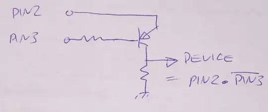
The diode may not be necessary, depending on the power supply's design. Many have diodes internally, so the external diode would be redundant. This isn't often specified in the datasheet, but can usually be determined by inspection. If you're not comfortable with electronics, I don't recommend omitting the diode of course, but just to mention that it is possible.
You can also use a braking resistor, simply across the supply +30V to GND. This would normally waste an obnoxious amount of power (or perhaps even overload the supply, if the motor must stop in a hurry), so it can be wired to a switch to turn it on only while braking is expected (assuming a microcontroller is running operations here), or a voltage comparator circuit so that it comes on automatically when the voltage rises above the nominal maximum level.
An automatic braking resistor circuit might look like this:
https://www.seventransistorlabs.com/Images/ShuntBallast.pdf (Source: my website)
R4/R8 ratio sets the voltage threshold (yours will need to be a bit higher), R7 sets hysteresis (difference between rising and falling thresholds). R1-D1 and sometimes IC1 draw some idle current from the supply, which may be a concern for a battery-operated system. (My use-case is battery powered, hence the switch.) You may not need local capacitors as the H-bridge may have enough on it already, just wire this nearby. Capacitance sets the oscillation rate, which should be at most a few kHz maximum at full load. The number of transistors and resistors required, depends on what you have available, and how much power you need to dissipate worst case.
The circuit switches on and off repeatedly, so the total resistance should be dimensioned for worst case maximum sustained backflow plus some margin, and they will merely come on from time to time as needed. My case had quite a beefy load, but absorbing 10J might not need much, depending on how fast that spring snaps back, and any other potential actions.


