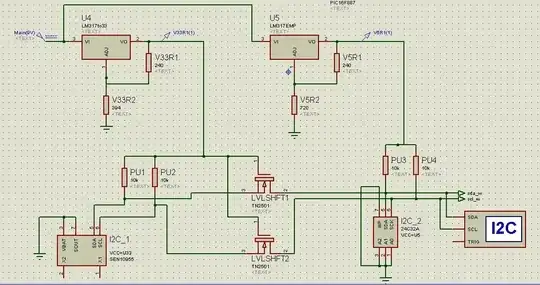
I am currently designing a circuit that can record data from a sensor and save the data recorded into an EEPROM. My two devices (EEPROM and for testing purpose a RTC) are connected via an I2C bus to a PIC16F887 µC. However, the two devices voltage operating range is not the same (5v for the EEPROM, 3.3 for the RTC), and my battery is a 9V battery.
Therefore I designed an electronic circuit with a level shifter composed of MOSFETs for the SDA/SDL wiring. On top of that I added two LM317 voltage regulator to power the devices (9V->3.3V and 9V->5V). As I am not an expert in designing such things, I would appreciate if you could glance at what I made and tell me if I did something horribly wrong!