3

I have an ESP32 with a DAC pin that outputs a variable voltage between 0 and 3.3 V.

I need to convert this signal to another voltage range: between -15 and +15 volts. This signal need to drive around 1 A (the more the better).

What is the best way to achieve this in the simplest possible way?

Note: the output pin of the ESP32 does not have to be DAC, it can also be PWM, SPI, I2C, etc. if it makes the solution simpler.

Damien
  • 141
  • 4
  • 4
    Perhaps you’d be better off buying a small bench power supply with serial interface. – Spehro Pefhany Apr 03 '23 at 15:19
  • 1
    It would be helpful if you update the question with some more information about the nature of the signal (especially how fast will it change) and what the output will drive. It seems like you might want to use a small reversing DC motor driver. These can have I2C or SPI interface. – Theodore Apr 03 '23 at 20:32

2 Answers2

9

You want to translate 0 V to 3.3 V to -15 V to 15 so you need to offset and scale.

The scale is what you need to bring the input voltage range to the output voltage range.

$$ \frac{15V - (-15V)} {3.3V - 0V} = \frac{30}{3.3} = 9.09...$$

The offset is what you need to bring the low input voltage down to the low output voltage, so -15 V in this case. If you do the offset before the scaling you can make the offset -1.65 V, since you want your signal centered at 0 V and 1.65 V is half of 3.3 V.

You can use a subtractor circuit with gain of 9.09... to subtract 1.65 V from your input voltage. the resistor ratio for that gain is 100:11, so we'll use 100k and 11k. A simple divider will get the 1.65 V reference from the micro's 3.3 V supply, two 22k resistors will give us an equivalent of 11k. The output of the opamp can be buffered with some transistors to get more current, I've used a simple class B arrangement here. The opamp could be a different type, with a rail-to-rail one you could lower Vcc and Vee. The output is into a 15\$\Omega\$ load so the current is +/-1 A. Note that the buffer is in the feedback loop.

enter image description here

GodJihyo
  • 17,628
  • 1
  • 16
  • 45
  • 1
    The OP or whoever build this circuit should keep in mind that these transistors will dissipate up to 15W of power. – Jan Kundrát Apr 03 '23 at 17:25
  • 3
    @JanKundrát In simulation they come out at around 6.5 W max. each. Note that I've updated the schematic. – GodJihyo Apr 03 '23 at 18:11
5

The relationship you require between input and output is:

$$ \begin{aligned} V_{OUT} &= \frac{15}{1.65} \times (V_{IN} - 1.65) \\ \\ &= V_{IN} \times 9.09 - 15 \\ \\ \end{aligned} $$

Consider this design:

schematic

simulate this circuit – Schematic created using CircuitLab

It has the relationship:

$$ \begin{aligned} V_{OUT} &= V_{IN1}\left(1 + \frac{R_2}{R_1}\right) - V_{IN2}\frac{R_2}{R_1} \\ \\ \end{aligned} $$

Those last two equations have the same form (something times \$V_{IN1}\$ minus something times \$V_{IN2}\$), and these terms can be equated:

$$ \begin{aligned} 1 + \frac{R_2}{R_1} &= 9.09 \\ \\ V_K \frac{R_2}{R_1} &= 15 \\ \\ \end{aligned} $$

The first one allows us to choose some resistances whose ratio is 9.09. If I arbitrarily set \$R_1 = 10k\Omega\$, then \$R_2\$ is:

$$ \begin{aligned} R_2 &= (9.09 - 1)R_1 \\ \\ &= 81k\Omega \\ \\ \end{aligned} $$

\$V_K\$ is some constant potential whose value is:

$$ \begin{aligned} V_K &= 15\frac{R_1}{R_2} \\ \\ &= 1.85V \end{aligned} $$

Plugging all these values into our amplifier, we get:

schematic

simulate this circuit

That produces the desired offset and amplification:

enter image description here

There's just the little problem of not having a source of 1.85V, so assuming you have a 3.3V source, we can make one with a pair of resistors as a potential divider. The only issue is that if we replace source V2 with this derived 1.85V, then connect R1 to it, the total impedance of R1 and our divider will be greater than 10kΩ, messing up our carefully engineered gain.

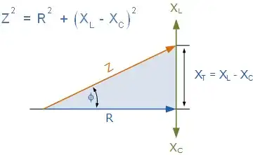
However, if we can make a resistor potential divider with equivalent source impedance of 10kΩ then we can dispense with R1, and replace it altogether with our divider. In other words, we need to create a potential divider, which together with a 3.3V source, will have a Thevenin equivalent exactly like V2 and R1 above:

schematic

simulate this circuit

There are two conditions. Firstly, the values R3 and R4, if combined as if they were in parallel, should be 10kΩ. Secondly, the voltage at the junction of R3 and R4 should be +1.85V. These two conditions are written algebraically like this:

$$ \begin{aligned} \frac{R_3 \times R_4}{R_3 + R_4} &= 10k\Omega \\ \\ 3.3V \times \frac{R_4}{R_3 + R_4} &= 1.85V \end{aligned} $$

I won't show my working to solve these equations for R3 and R4, but they are:

$$ \begin{aligned} R_3 = 17.8k\Omega \\ \\ R_4 = 22.8k\Omega \\ \\ \end{aligned} $$

Replacing R1 and V2 with the equivalent:

schematic

simulate this circuit

If you use a power op-amp, like the PA74 there may be nothing more to do, except take care of heating. Maximum power dissipation will happen when the load is sinking/sourcing 1A, and has half the total supply across it, 20V. That's \$P=IV=20W\$, and will require beefy heat-sinking, and probably forced-air cooling.

If you don't have a power op-amp, and can't get one, then you'll have to build your own buffer stage, to produce the same voltage, but capable of sinking and sourcing 1A. Here I will do this with a push-pull arrangement consisting of bipolar transistors.

A typical BJT has a current gain of about 100, which would require 10mA of base current in order to source/sink 1A. That's really at the edge of what we can ask of your average op-amp, so I'll use darlington pairs to increase current gain, and relieve the op-amp of any significant current demand. You'll need an op-amp capable of outputting at least ±17V to get the full ±15V output swing:

schematic

simulate this circuit

The buffer stage is placed inside the op-amp's feedback loop, so that it's getting feedback from the buffer's output instead of its own. This kind of setup can be quite unstable, and oscillate somewhat (especially with a capacitive load). I try to mitigate this with C1 for some frequency compensation, but this is probably insufficient. You'd need to do some serious stability analysis, and employ better frequency compensation than this.

R5 protects the op-amp by preventing it sourcing or sinking its maximum short-circuit current in the event you do something silly at the output.

Also there's a huge dead-zone near 0V out, where neither transistor is on, which could lead to instability, and will definitely cause crossover distortion, but that's way to deep to go into here.

Q2 and Q4 can get very hot, since they could potentially dissipate 20W. This is the price you pay for a linear power stage like this, with such a large output voltage range and high current capability. They must be mounted on big heat-sinks, and probably cooled with a fan.

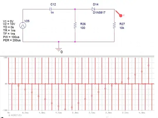
Here's the output (orange) of that circuit when a sinusoidal input (blue) varying from 0V to 3.3V is applied at IN

enter image description here

Simon Fitch
  • 27,759
  • 2
  • 16
  • 87
  • Questioner wants "simplest possible way." Apex PA-162? Of course, with resistor dividers there's no accounting for tolerance. So I wouldn't expect accuracy. [Here's a quick calculation](https://i.stack.imgur.com/Xo2EC.png) seeing what the (-) input looks like with 2% resistors given the two outputs of +15 to -15. – periblepsis Apr 03 '23 at 21:13
  • 1
    @periblepsis Thanks, I updated my answer to suggest a power op-amp. I think a bigger issue (bigger than resistor tolerances) is power supply noise, which R3 and R4 inject directly into the system. A better approach to derive 1.85V is a TL431 or similar, but I'm not sure if this falls within the scope of the question/answer. Then there's frequency compensation, which is by far the greatest concern, and definitely not within the scope. – Simon Fitch Apr 04 '23 at 04:21
  • 1
    @periblepsis Also I think that the low open-loop gain of a typical power op-amp is likely to have a big effect on accuracy and linearity. So, I'll just leave that here. – Simon Fitch Apr 04 '23 at 04:23
  • Yeah. The questioner wants "simplest possible way" and what I started and you added to says that "reality impinges and nothing is really `simple`." Our imaginations make circles and squares seem perfect. We survive in a state of continual denial. No matter how hard we work nor how experienced we become, unknown unknowns still arise where we don't expect them and we never can get to the point where we avoid failing to neglect some detail we wish we'd seen. I hate it when I see someone say they want the simplest solution to anything. Grates on me. No one knows what the future brings us. – periblepsis Apr 04 '23 at 11:35
  • 1
    @periblepsis Ironically, those unknowns are one thing I love about electronics; that it isn't simple, something always pops up to mess you around. If it was easy nobody would need us. At least, that's what I tell myself. – Simon Fitch Apr 04 '23 at 13:00
  • I think it's what attracts us all, perhaps. Or should. – periblepsis Apr 04 '23 at 19:08
  • Thank you for this step-by-step explaination, it is very valuable ! – Damien Jul 20 '23 at 09:43