I'm trying to create a basic 4-button battery powered remote. The logic behind it is that when one of the buttons is pushed it pulls the base of the PNP low thus turning on power to the circuit. The Arduino then takes over holding the base/gate down using a digital pin, it detects which of the 4 buttons is pressed, sends that info over LoRa with battery level using the RA-02 then pulls the PNP up turning everything off and conserving battery power. The current materials used:
- ATmega328, the same uC used in the Arduino Nano.
- RA-02 for LoRa communication.
- 4 momentary simple push buttons.
- PNP transistor or FET
- resistors and diodes and whatever other passive components you think is needed.
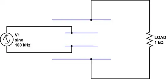
simulate this circuit – Schematic created using CircuitLab
In the above schematic the radio is ignored since it's unimportant for the question.
I'm able to use each one of the four buttons to momentarily turn on the circuit, and keeping it on is not the issue.
The issue appears when I make the connection between even one of the buttons to one of the digital pins of the Arduino: it partially turns on the circuit with 2-3 ma current draw (uCurrent ranger).
Pin 5 of the Arduino keeps the circuit on while transmitting, pins 6-9 are for checking thd button state. I used diodes to prevent all pins of the Arduino from going low when one of the buttons is pressed. I used a 10 kΩ resistor to pull up the transistor to keep it off in a known state.
I'm not really sure about why the circuit is "leaking" when I connect any one of the four connections between the ATmega328P and the buttons.
I tried pulling the Arduino pins up using external resistors from 10 kΩ to 2 MΩ; it might vary the leakage but never resolves it. I tried adding resistors in series between the ATmega328P and the buttons instead of direct wires and that helped a lot, but it needed high value resistors like 1-2 MΩ and never stopped the issue completely; I stil get a few μA leakage which to me is not really a circuit that is off.
I have seen other answers on here but they're all using one button, and the main question is auto off in that case, whereas here it's a partially turned on circuit.
I don't want to leave the circuit in sleep mode since I might add other sensors that are power hungry even in sleep so I really would love it if someone has an idea to resolve the issue.