I am trying to design my electric vehicle charging station. There are some examples on net but they are designed by using relays at live and neutral outputs.
The main purpose of this design is to cut both neutral and live output.
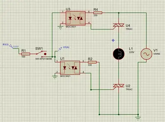
Trying to implement this with triacs and zero-crossing optocouplers. On proteus sim it seems to be working but I would like to be sure if I need to add/change this design.
Is it OK to use TRIACs like this? Any comment/help would be appreciated.
Note: Proteus screenshot below is just to simulate power side of things. Ground fault detection and pilot signal circuit will be added on final design.
Also ground at bottom added for crash proof on sim. Won't be there on the PCB.
Edit 1:
Thanks for all comments, really helping me out.
After MikroPower's answer, I made below changes:

So I think I need to control both high current relays.
- When enabling output:
SW1 & SW3 ON, after few secs SW2 ON & SW1 OFF. - When disabling output:
SW1 ON & SW2 OFF, after few secs SW1 & SW3 OFF.
Also tried reverse mains on sim, and seems to be working.

So what do you think about last design?
