The BQ2054, like all charge control ICs that I have seen, regulates the charge current, but has no idea what C rate is.
Some ICs have what they call a "current programming" resistor connection. The BQ2054 (and many other such ICs) monitors the maximum current by measuring the voltage across a low value resistor.
From the datasheet:
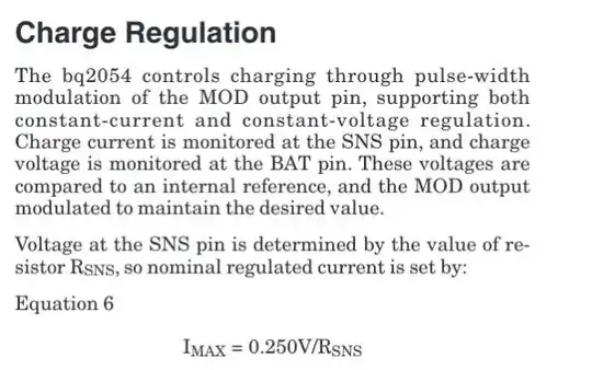
You can rewrite the equation to find the resistor value needed for a specific maximum charge current:
\$R_{SNS} = \frac {0.250V}{I_{MAX}}\$
You (as the circuit designer) have to determine \$I_{MAX}\$.
Say you have a one ampere hour battery. A C-rate of one would charge the battery in one hour - you need a charge current of 1A, so you would do the calculation for the BQ2054 and find that you need a 0.25 ohm resistor. If you wanted to charge your battery at a C-rate of two, that would be twice the current as for the C-rate of one - that's 2A of current. You would need a sense resistor of 0.125 ohms.
Whether or not the BQ2054 is sufficient for your experiments will depend on the capacity of the cells you want to test and the C-rates. You are limited by the maximum 2A charge current of the BQ2054.
You could charge a 100 milliampere hour cell at any C-rate up to 20C using the BQ2054. You could charge a 1 ampere hour cell at a maximum of 2C with the BQ2054.
I couldn't begin to even guess how applicable such experiments with small capacity cells would relate to the larger, higher capacity cells used in electric vehicles.
