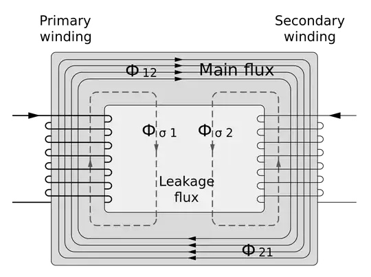
I'm trying to simulate an induction heater, and I'd first like to start with the load. Sorry if this is a little wordy...
I understand the coil and workpiece are treated as a transformer, where the workpiece is treated as a single-winding secondary with some series resistance. Here's how I've made my transformer equivalent of my application so far...
First, I say that the work coil has N turns and the workpiece has 1 turn. My work coil has 12 turns, so I have a 12:1 transformer. From this, I say that the inductance ratio will be 12^2:1^2, or 144:1. In retrospect, this might be an oversimplification. I don't know.
Second, I measure the inductance of my transformer with the secondary open to be 12µH (aka my work coil without the workpiece is 12µH) and with the secondary closed/shorted to be 5µH (aka 5µH with workpiece in work coil).
Now, I know my secondary winding (workpiece) can be modeled as a 12µH/144 = 83nH inductor. I also know my coupling coefficient is k=sqrt(1-Lshort/Lopen), or k=sqrt(1-5/12)=0.76=76%. This gives the following result:
Not sure about my R. This wonderful LCR meter testing at 200kHz tells me 5µH and 0.1Ω for the work coil + work piece together.
Something must be wrong, because my resonant frequency in LTSpice has now changed by a lot, as if only the first inductor is considered, as if there's zero coupling with the secondary. When I change its value to 5µH, it goes back to being what I would expect...darn.
I posted on Reddit (link to post, same stuff as here), and I was told a more realistic model looks like this:

In my case, R_FE=0 (no iron losses)...and then I don't know the rest.
Really want some clarity here. Please say if proceeding with series LR arrangement with L=5µH and R=0.1Ω would be best.
Thank you in advance to any kind souls.
