0

Is there a way to interface a digital potentiometer with this circuit so that the actual potentiometer could be replaced with a dual NO push button control?

I have thought about this and it would be much easier to use one of these circuits to control the duty cycle of a PWM fan. I many years of experience working with potentiometers with wipers becoming unable to function over time, and that is why I would like to replace a knob with push buttons.

If there is a way to do this and someone knows where to find a diagram for this, please let me know.

This is a modification of the circuit in the question here: Control duty time and frequency with different potentiometers using one 555 timer.

EDIT:
I do not want to use any form of NAND gate whether it be CMOS or TTL. I am asking how you would directly add a digital potentiometer to a 555 timer as a replacement for R2 without using any other form of chip in the circuit except for a potentiometer IC and a 555 timer IC.

Adding any further chips would make that circuit more complex than it needs to be.

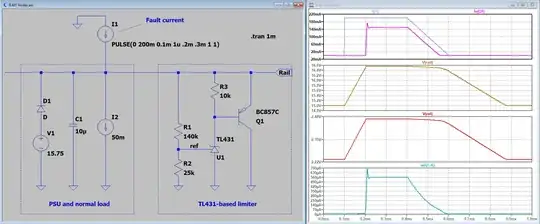
I need to be able to interface the left circuit to the right one in the image below. PWM Circuit Sections

Image adapted from AD5116 datasheet, figure 1 & Electronics Tutorials, 555 Timer Tutorials

As for any circuit that uses an MCU processor because that is getting a little more complex that what I need for what I am trying to do. That is to control some DC powered PWM fans for use in a paint box for airbrushing. As for the use of a potentiometer, I have experience with those and over time they either deteriorate from use or get crud in them that will bind them. In a paint booth for airbrushing the paint from an airbrush is that crud that I need to avoid getting inside of any standard potentiometer.

SamGibson
  • 17,231
  • 5
  • 37
  • 58
  • 1
    `Is there a way to interface a digital potentiometer?` has a simple `yes` for an answer ... if you want more information, then ask `How to interface a digital potentiometer?` – jsotola Mar 22 '23 at 01:45
  • 1
    I would just get a better pot honestly. A digital pot requires a lot of extra baggage. – DKNguyen Mar 22 '23 at 01:46
  • There used to be Xicor nonvolatile digital potentiometers that had up/down inputs. I'm sure something like it still exists, and if not then very simple logic could translate button pushes to I2C up/down commands. – Kuba hasn't forgotten Monica Mar 22 '23 at 02:20
  • While possible, will it make sense to add button debouncing circuitry and a digital pot, to control a duty cycle of a 555 timer? There has got to be better and cheaper options, such as replacing all the above with the cheapest and tiniest MCU to generate button controlled PWM. – Justme Mar 22 '23 at 06:28
  • PaulRobinson - In a [comment](/posts/comments/1782979) on an answer, you said: "*I will not use a CMOS IC because I know how easily those can be killed by static electricity.*" I'm responding here, as the point is not specific to that answer. The digital potentiometer you specified (AD5116) (and all the others that I know) are ESD-sensitive (see page 6 of the [AD5116 datasheet](https://www.analog.com/media/en/technical-documentation/data-sheets/ad5116.pdf) for the official warning). It seems you have contradictory constraints - wanting to use a digital potentiometer but not allowing CMOS ICs. – SamGibson Jun 08 '23 at 03:59

2 Answers2

1

An AD5220 can do it with a little logic. Something like this:-

schematic

simulate this circuit – Schematic created using CircuitLab

The CD4093B contains four NAND gates with Schmitt trigger inputs. In this circuit we only use two of them. The top NAND gate is configured as a clock generator running at ~10 Hz (frequency determined by C1 and R1), controlled by the lower input which must be high for oscillation.

The bottom NAND gate output goes high if either push-button is pressed. If the 'down' button is pressed it also pulls the AD5220 U/D pin low to count down (otherwise it counts up).

One limitation of this design is that the AD5220 always starts in the center on power up. Non-volatile digital pots with EEPROM memory are available, but all the ones I looked at used an I2C or SPI interface. If the pot needs to retain its setting when powered off it might be better to use a small MCU to generate the PWM signal directly, eliminating the need for the digital pot and 555 timer as well as several other components.

Bruce Abbott
  • 55,540
  • 1
  • 47
  • 89
  • This is not what I was asking for or about. Please check the newly added image above with the circuit sections in it that I have been trying to figure out how to interface them together. Not only that, I am familiar with CMOS and I know how easy it is for them to get zapped by static and frying them. TTL is better but I still do not need the circuit that you included above as your answer. – Paul Robinson May 25 '23 at 22:44
  • 1
    Actually it is what you were asking about, except you have found an IC that doesn't need any extra circuitry. Congratulations! Just wire it in place of the pot and you're done. Only problem is it comes in a tiny LFCSP package. Hope you can find a breakout board for it. – Bruce Abbott May 26 '23 at 01:15
1

Something like this should work, where R3 represents the AD5116 80kΩ version.

It's necessary to regulate the 12V down to 5 because the digital pot cannot handle more than about a 5V supply. If your fan is 5V it is not necessary.

A CMOS version of the 555 would probably be better.

M1 should be a logic level MOSFET with switching characteristics specified for 4.5V Vgs and adequate rating for the fan.

With the given components, the PWM frequency is about 20kHz. Adjust C2 for higher or lower frequency.

schematic

simulate this circuit – Schematic created using CircuitLab

Spehro Pefhany
  • 376,485
  • 21
  • 320
  • 842
  • I will not use a CMOS IC because I know how easily those can be killed by static electricity. – Paul Robinson Jun 08 '23 at 02:56
  • 1
    @PaulRobinson - Re: "*I will not use a CMOS IC because I know how easily those can be killed by static electricity.*" The digital potentiometer you specified (AD5116) (and all the others that I know) are also ESD-sensitive (see page 6 of the [AD5116 datasheet](https://www.analog.com/media/en/technical-documentation/data-sheets/ad5116.pdf) for the official warning). It seems like you have contradictory constraints - wanting to use a digital potentiometer but not allowing CMOS ICs :( – SamGibson Jun 08 '23 at 03:48