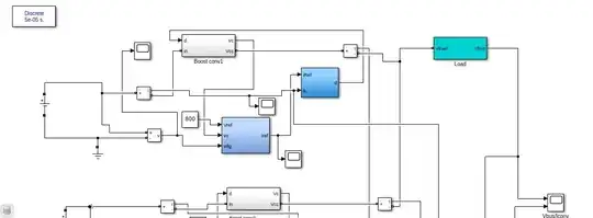
I am trying to simulate the droop control in an isolated DC micro-grid as shown in the figure. There is a constant voltage across the load as expected (~800 V), but the output power is zero. I think the current is not properly configured. I've been stuck on this problem for a week now.
Edit1: 
 First of all please ignore all the scopes which are randomly placed to see which part of the system was erratic. So yeah, going in depth, I have used 2 DC voltage sources which supply 200V each. It is directly given to a current measurement (according to this paper https://ieeexplore.ieee.org/document/6452563/authors#authors). From the current measurement it is given to Boost converter but I will come back to this later. The voltage source is given to voltage measurement which gives voltage signal to the droop controller part.
  The reference voltage is the voltage that is to be maintained at dc bus. So it is given as 800V. And the Vdg is the input voltage. Vo is the output voltage from boost converter which again I'll come back to at a later point. In the PI controller the proportional constant is given as 0.75 and integrator as 12.73 which is directly taken from the paper tbh By modelling the Droop control block, we get the Iref, which is given to the hysteresis block. (I'll edit this question again in a short time, please don't close this question, I'lll finish it)
