18

I have two sets of almost identical-looking capacitors which show different behaviour: pair of capacitors
The ones on the left (which are definitely these MLCCs) act as I would expect, but the ones on the right (which we think were a previous order of the same but cannot be sure) have odd effects in an RLC circuit as below:
schematic

simulate this circuit – Schematic created using CircuitLab

At the resonant frequency, the trace of \$V_\mathrm{FG} - V_\mathrm{r}\$ shows a triangle wave: enter image description here
and consequently the FFT of the \$V_\mathrm{r}\$ channel shows odd harmonics for the "bad" capacitor: enter image description here
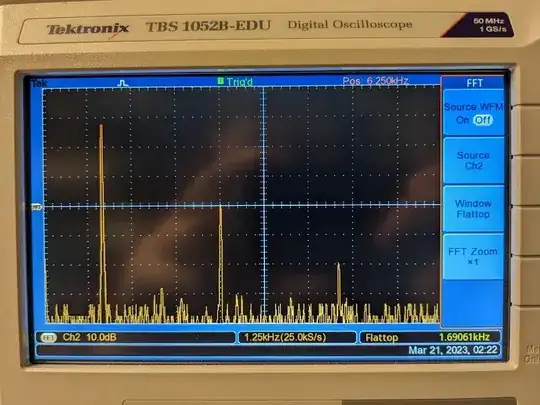
but the good capacitors give an almost pure sine as expected when swapped

enter image description here

They both measure the same approximate capacitance (100 nF) on a multimeter. Also, when sweeping the frequency across the resonance, the "bad" capacitors have a much faster phase change when going slightly above the resonant frequency. What imperfection or property of these capacitors could be causing this nonlinear behaviour?

llama
  • 548
  • 3
  • 9
  • 1
    Very interesting. Could you see if this behavior persists at lower applied voltages? Say 100mV or 500mVp-p? I don’t expect a change. Also does it hold at varying applied frequency? I can’t think of a mechanism for this. – 65Roadster Mar 20 '23 at 21:53
  • I'd try a few things. You or we need more data. Remove the 120Ω. It will qive you larger signals to work with. Run your test again on both capacitors. The - is a calculation, so decrease the time resolution on the scope to get less than two complete cycles on waveform. I'd try two inductors in series or parallel to change resonant frequency and see impact. – StainlessSteelRat Mar 20 '23 at 22:14
  • @StainlessSteelRat I'd also turn on/up the averaging if it's compatible with FFT on that model - but the harmonics are pretty clear already. I wouldn't want to zoom in too far before FFTing either – Chris H Mar 21 '23 at 09:14
  • 1
    +1 for the funny triangle graph – fraxinus Mar 21 '23 at 14:08

6 Answers6

13

Classic type 2 dielectric behavior. All capacitors of this class have a voltage dependency (ferroelectric saturation), meaning C decreases as |V| rises. Evidently you have a particularly sensitive example.

Tolerable voltage, for a given amount of C loss, varies widely with material type (temperature coefficient code), chip size, and construction. Basically it depends on the thickness of layers, but thickness and layer count are up to the manufacturer. So you really just need to look up the characteristic sheet for the part -- if you know the part number, and if the manufacturer provides such.

Random junkbox parts, you have very little hope of that, so, at best you can characterize them. Which is a bit of a PITA...

Most capacitors aren't too sensitive, but especially larger values, and at higher voltages, the decrease can be surprising. It's a common pitfall.

Type 1 (C0G, etc.) ceramics, and film capacitors, do not exhibit C(V) dependency, so are a good choice for resonant circuits.


Interesting aside about the circuit: it has hysteresis with respect to frequency. As amplitude grows, average capacitance (averaged over a cycle, roughly speaking) drops. So as you adjust frequency down, it seems to stay in resonance, and amplitude continues to increase. Eventually, amplitude peaks, then frequency drops below the passband (given the driven amplitude) and amplitude suddenly drops. Ramping frequency back up again, a much smaller resonant peak is seen. Not very useful, but a nonlinear curiosity.

Tim Williams
  • 22,874
  • 1
  • 20
  • 71
  • 4
    Coming from an experimental physics background, very visible non-ideal capacitance of a capacitor at under 10% of its rated voltage is definitely not something I would have guessed, thanks in part to people like the denizens of this SE accounting for/avoiding it in the equipment I've used. But this is definitely it, the nonlinear behaviour becomes negligible if the amplitude is reduced to 500 mV or less – llama Mar 21 '23 at 15:58
  • 2
    Indeed, capacitors are commercially available showing significant change within just a couple of volts, and less than 10% capacitance remaining at rated voltage; the voltage rating is only a survival rating, unrelated to electrical characteristics. FYI, inductive components are the same way: ferrite beads are directly analogous, having a thermal rating only, which is unrelated to impedance under bias; inductors however are sold with a rated saturation current (usually measured at -10 to -50% inductance). – Tim Williams Mar 21 '23 at 17:11
11

Y5V is a nasty Class II dielectric- the worst much in present-day use, I think.

I wouldn't even use it for a bypass capacitor let alone resonate something with it (it might be acceptable for a toy that never has to work over much of temperature range). +20/-80% over voltage/temperature and a fast aging rate.

Possibly they substituted something like X5R- on one of the orders. A better dielectric will meet all the specifications of the crummy one easily. Or maybe the construction is just different (perhaps from different factories). If you want nice behavior where the capacitance value and loss characteristics matter, NP0 or a film cap would be best.

Y5V is bad enough that a friend of mine suggested the possibility of making an amplifier with it.

The voltage coefficient varies greatly with manufacturer and construction, here is a Z5U MLCC from a the same maker with similar voltage rating:

enter image description here

The other characteristics are similarly unpleasant:

enter image description here

Spehro Pefhany
  • 376,485
  • 21
  • 320
  • 842
  • 1
    You *can* still get Z5U capacitors, which are even worse than Y5V, but I'm not sure why anyone would ever want them today. I'm not sure why they're still being made. – Hearth Mar 21 '23 at 02:35
  • Ah I was confused about that +20/-80 spec, didn't realise it was for different conditions rather than just a ludicrously large bin for part-to-part variance – llama Mar 21 '23 at 16:00
  • 2
    @Hearth Very slow random number generators maybe. – pipe Mar 21 '23 at 16:38
  • 1
    _Y5V is bad enough that a friend of mine suggested the possibility of making an amplifier with it_. Yeah, it could be interesting for a parametric amplifier! – Massimo Ortolano Mar 23 '23 at 14:11
4

Ceramic capacitors have different dielectrics and the dielectric is labelled by class, not material composition. So that means even two capacitors both labelled as X7R might actually be made of different materials.

DKNguyen
  • 54,733
  • 4
  • 67
  • 153
3

Either the capacitance or dissipation factor of the capacitor is voltage dependant. And in the case of the dissipation factor, really poor. With your cap meter put a good cap (larger, say 1 uF) in series with the suspect cap like this meter neg - test cap - good cap - meter pos. Then you can use a resistor (say 100K) connected to the junction of the caps and add DC bias to the test cap and see if its capacitance changes with say 0, 1 and 2 Volts across it. You can also try measuring its leakage, but you need to know its voltage rating. Any way hook it up in series with the most sensitive current meter that you have to a power supply. Bias the cap at its working voltage, you should measure no current. However whatever is happening to create the distortion it needs to be a (changing) function of the applied voltage.

Doug Crowe
  • 292
  • 4
1

In a series RLC circuit operating at resonance, the applied voltage (your V1) (V_FG), should equal your Vr.

In a series RLC circuit operating at resonance, Vin equals Vr.

Since your input voltage V1 does not equal Vr (you get a triangle wave), you have something important missing from your equations.

The missing part of your equations appears to be a resistive portion of capacitance or the resistive portion of your inductor.

Since you have not mentioned that your inductor has a core other than air, it seems reasonable that the difference in your output lies with differences between the capacitors.

Therefore it seems reasonable that the difference between your capacitors is a non linear component of resistance in the capacitors dielectric.

Marla
  • 5,220
  • 1
  • 22
  • 31
-3

They might be rated for different voltage, or they may be made from different material.

Justme
  • 127,425
  • 3
  • 97
  • 261