4

I have this circuit diagram of an AM modulator and I am trying to understand what is going on.

I know that the c(t) is taken from the collector of transistor Q1 and the multiplication of signals : m(t)c(t) is taken from the collector of transistor Q2.

I want to know at what point and how the two signals m(t) and c(t) are multiplied.

enter image description here

JRE
  • 67,678
  • 8
  • 104
  • 179
  • Be careful of what you "know" about Q1,Q2 output. Both contain a version of *m(t)c(t)*. – glen_geek Mar 19 '23 at 13:15
  • @glen_geek Thanks for letting me know, I knew I am wrong somewhere. Can you please elaborate on it? – Ashwin Singh Mar 19 '23 at 13:46
  • Ashwin, Andy's answer is good... **gain of the differential pair** (Q1, Q2) depends on current supplied by Q3. And Q3 is a fairly linear stage. Q1&Q2 collectors both contain many frequency components (50 Hz, 1kHz, 950Hz, 1050Hz, 2950Hz, 3000Hz, 3050Hz...and more). The diff-amp 741 stage eliminates 50Hz component, leaving the desired 950, 1000, 1050 components (plus the other higher-frequency components too :-( – glen_geek Mar 19 '23 at 16:44

1 Answers1

6

I find this 2-quadrant (Broadcast AM) multiplier explanation to be quite useful: -

enter image description here

What it's basically saying is that if you change \$I_{EE}\$ you can change the slope of the graph: -

enter image description here

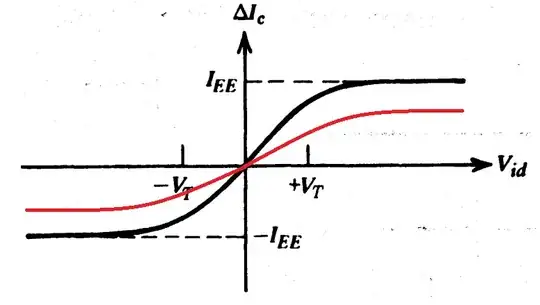
I've drawn the red line on the graph above to indicate a lower value of \$I_{EE}\$. The linked document also goes on to show how \$I_{EE}\$ is "varied" using another transistor: -

enter image description here

I want to know at what point and how, are the two signals m(t) and c(t) multiplied.

It's all done around Q1, Q2 and Q3 in your circuit. The differential amplifier that follows Q1 and Q2 converts the differential output of Q1 and Q2 to a single ended output.

Images above taken from Analog Multipliers by School of Electronic and communications engineering.

Another useful link from Analog Devices MT-079 Analog Multipliers.

Andy aka
  • 434,556
  • 28
  • 351
  • 777
  • 1
    Thank you for the explaination , I was very wrong about me knowing about the Q1 and Q2 part, i understand whats going on in the circuit now – Ashwin Singh Mar 19 '23 at 15:06