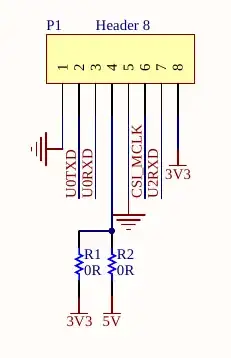
This is the official schematic of ESP32-CAM:
Here is the area of interest:
Why does this schematic imply that the 3.3V and 5V power lines are shorted through 0 ohm resistors? The masured voltage at P1 pin 4 is 3.3V.
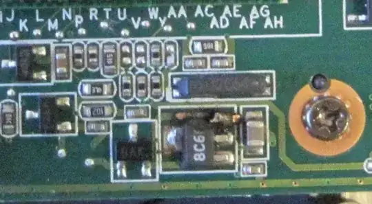
I took a closer look at the PCB and noticed that there are unpopulated resistor pads. Is this a normal way to indicate 0 ohm permanent (factory configuration) jumpers on the diagram? If so, is there a clearer way to indicate that only one of these resistors is present?


