0

So, There is this schematic that a previous collegue made for a project that I took over that have some EMC problems (Burst/EFT). The problem is that 12V on the secondary side of the transformer(not shown i picture. off to the right). The voltage drops when burst test is being done.

Is this Gas Discharge Tube (PN 2051-09-SM-RPLF) correctly mounted?(marked with red arrow).. Should it not go from Line to GND instead of over the "choke"? Is there any reason why one would connect it like this "over" the choke? Or have he done a misstake?

Also, (since I am anyway asking you for help) any tip for improvement I could try to pass the burst test?.. Any help would be appreciated.
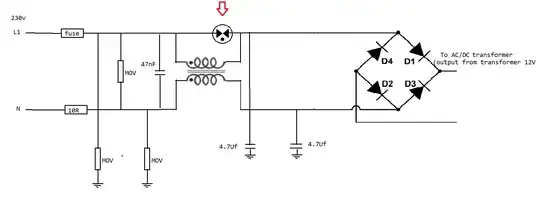
enter image description here

aaq
  • 131
  • 6
  • There is no transformer, or there are errors drawing it. It looks like there is a common mode choke so the label that says 12V is really 325V. Unless there is something else not described. – Justme Mar 18 '23 at 23:42
  • Transformer not showed in picture. It is to the right of the bridge rectifier. I just made a paint image showing the part i am wondering about. – aaq Mar 18 '23 at 23:48
  • There seems to be some things missing from your sketch. There should be a transformer to step the 230 VAC down to 12 VAC. Now assume the gas discharge tube goes to N, or chassis. When the gas discharge tube fires, it's going to short the 230 VAC to N (or chassis). This will remove the AC input to the (hypothesized) transformer and cause the 12 VDC output to drop out. Maybe the same thing happens if one of the MOVs trigger during the burst test. – SteveSh Mar 18 '23 at 23:52
  • @SteveSh MOVs clamp the overvoltage without "folding back" like a GDT does, so those are unlikely to be the issue. – Jonathan S. Mar 18 '23 at 23:54
  • Also, I am not familiar with your "burst test". Could you provide a brief summary of what that test does? – SteveSh Mar 18 '23 at 23:55
  • @SteveSh It whacks the circuit with very fast (50ns) common-mode transients... The kind of transients that could easily couple into and upset a SMPS control chip. – Jonathan S. Mar 19 '23 at 00:01
  • So a type of CS test? – SteveSh Mar 19 '23 at 00:15
  • You say "transformer" but did you mean "SMPS"? Pure passive transformers, the lone component, cannot transform DC, but an active SMPS can. An SMPS contains a transformer, but much more also, to implement this function. – Tim Williams Mar 19 '23 at 07:09
  • There are other errors shown, by the way: MOVs cannot be used to GND without a GDT in series; 4.7uF (mind capitalization) is WAY too much line-to-ground leakage; and note the 10R must be fusible type, and then I guess the equipment needs to be marked as double fused. (I'm not familiar with current standards but these will be necessary for 60950-1 for example, if the equipment class is applicable.) – Tim Williams Mar 19 '23 at 07:21
  • yes, smps. but the capacitive reactance of a 4.7 uF capacitor for a 50 Hz signal is approximately 6.8 kΩ. is that really way to much? why would one need a GDT in series? – aaq Mar 19 '23 at 11:54

1 Answers1

0

The gas discharge tube is placed correctly. Its purpose is to clamp inductive spikes from the common-mode choke, which might occur when particularly bad common-mode interference is coupled into the device, or when mains gets disconnected.

If your "12V transformer" is actually a switchmode power supply, it's likely that it malfunctions during EMC testing. It might need more protection than you currently have, such as an extra differential-mode filter.

Jonathan S.
  • 14,865
  • 28
  • 50
  • OK, thanks. No, it´s a transformer + a IC with logic that controls it. – aaq Mar 18 '23 at 23:54
  • 1
    @aaq That's a switchmode power supply, and it's where your problem is. The IC is likely shutting down due to interference. You should try to filter its supply voltage, control signals, and feedback signals better as fast transients can couple into those and disrupt the IC's operation. – Jonathan S. Mar 18 '23 at 23:55
  • P.S. but this gas discharge tube starts leading at 90 volts already as far as I understand. Is that not way to low for 230VAC net? It would lead already for normal voltage ranges then...or?... – aaq Mar 18 '23 at 23:57
  • No, 90V is correct for this gas-discharge tube. In normal operation, the voltage across each winding of the common-mode choke should be very low - a few volts at most. You wouldn't expect 230V to drop over a piece of wire, after all. – Jonathan S. Mar 18 '23 at 23:58
  • oh, yeah right. True, not all volt ends up there. Good feedback. Thanks! – aaq Mar 19 '23 at 00:02
  • Anything else that I could try except for except for another choke? Concerned they are hard to pacth into the existing board since they are quite big... – aaq Mar 19 '23 at 00:07
  • The part of the circuit you showed is fine. You don't have to change it, and changing it won't help. You will have to re-design parts of the switchmode power supply. This will require a board re-spin. – Jonathan S. Mar 19 '23 at 00:24
  • OK, thank you for your help=) – aaq Mar 19 '23 at 01:06
  • Let us [continue this discussion in chat](https://chat.stackexchange.com/rooms/144712/discussion-between-aaq-and-jonathan-s). – aaq Mar 19 '23 at 11:43
  • Do you agree with the other comment I got?: "There are other errors shown, by the way: MOVs cannot be used to GND without a GDT in series; 4.7uF (mind capitalization) is WAY too much line-to-ground leakage; and note the 10R must be fusible type, and then I guess the equipment needs to be marked as double fused." Do I need another GDT? and is 4.7uF to much? – aaq Mar 19 '23 at 11:46