2

I am building a simple buck converter circuit with a current-mode control IC, the UC3843.

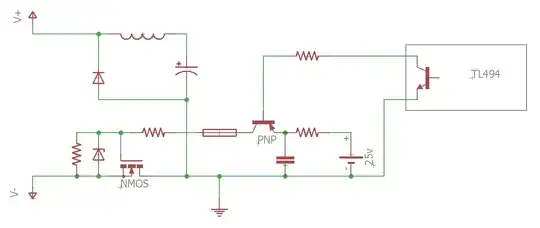
In the application note of the UC3843, a sample circuit is given:

In the application note of the UC3843, a sample circuit is given:

I am completely clueless about how these values should be set up. Also, is this even the correct circuit to follow?

I want an oscillating frequency of 100 kHz, which this circuit includes. Desired input voltage 24 V; desired output voltage 6 V; desired output current 1 A.
Raza Nayaz
  • 31
  • 4
  • 1
    *is this even the correct circuit to follow* <-- you posted it so you should have some idea where it came from (along with a circuit description) hopefully. So, you also need to specify input voltage range, desired output voltage and, desired output current. – Andy aka Mar 17 '23 at 20:46
  • 1
    The text at the top of your image is a clue: see "Closing The Feedback Loop", Buck Topology. – John D Mar 17 '23 at 20:58
  • 1
    Read and follow that datasheet and/or application notes? – winny Mar 17 '23 at 21:08
  • @Andyaka I edited the post to specify the mentioned points. – Raza Nayaz Mar 17 '23 at 21:12
  • @winny this circuit was given as an example in the application notes, but neither datasheet or application notes specify the points I am confused with. – Raza Nayaz Mar 17 '23 at 21:12
  • 2
    There is a design procedure in the datasheet; have you tried it? – ocrdu Mar 17 '23 at 21:13
  • @ocrdu which page/procedure are you referring to? I have been looking through the datasheet. (in case you are speaking about the fly-back circuit example on page 22, it's quite different) – Raza Nayaz Mar 17 '23 at 21:17

1 Answers1

0

Design of DC-DC converters it's not an easy thing. Not only you need manufacture specs of components used on the demo board they sell, but also you need the layout of the board where all the components are placed and manufacture special considerations (in case they will).

Vast majority of DC-DC converters designs uses a 4 or 6 layer pcb stackup to reduce EMI caused by switching noise, so take this into account at the moment of designing your board.

I found two links that I hope it helps you:

https://www.ti.com/lit/ug/sluu143/sluu143.pdf?ts=1679101241308&ref_url=https%253A%252F%252Fwww.google.com%252F

https://www.ti.com/lit/an/slua257/slua257.pdf?ts=1679102752310&ref_url=https%253A%252F%252Fwww.google.com%252F

  • the first one is a pdf archive with an official Texas Instrument design of a DC-DC buck converter using UCC38C43 ic. I suggest you to use this ic because it has the same characteristics of UC3843 and it has a reference design.

  • the second link is a pdf containing an application note and in page 6 you can see a comparation between UC3842/3 with UCC38C42-3 ic.

marcosbc
  • 414
  • 2
  • 11
  • thanks for the links that you shared. However, the ones you shared are awfully complex to what I am trying to build. Any other suggestions? – Raza Nayaz Mar 18 '23 at 06:21
  • 1
    @RazaNayaz Making a well-functioning DC-DC converter is awfully complex. If you’re not willing to invest the time and talent I suggest you buy a ready-made module. – winny Mar 18 '23 at 09:49