2

Why is everybody discourage from this paired NAND BJT Transistor "design"? I already saw a few posts where somebody asked something about the paired BJT NAND "design" and the answers only say: don't do it like this, use only one transistor and as many resistors as you want on the base for the inputs?

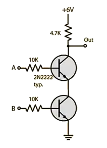
When I refer to the one/two BJT circuits, I mean these:

  • One BJT NOR: one bjt NOR

  • Two BJT NAND:

    two bjt NAND

To list a few:

And a further question, isn't the one BJT Transistor "design" bad, because current can also flow out of the gate input and interfere with other gates?

wolflu
  • 23
  • 6
  • Do you mean this image --> https://i.stack.imgur.com/dRPAA.png <-- please also show the "one BJT" design you refer to. – Andy aka Mar 17 '23 at 15:38
  • Sorry, that my initial post was unclear, I added the pictures of the circuits I refer to. – wolflu Mar 17 '23 at 15:52
  • None of them looks competitive even with classic DTL and TTL logic, due to poor switching response and power dissipation. The two resistors' solution is even worse, in switching times and delay times, due to a less sharp on/off state depending on input states. However, if what you need is a *single*, slow, and quick *high-voltage* gate, where you don't use other logic ICs, **maybe** it can do your work... For every other purpose it's way better resorting to an integrated solution – LuC Mar 17 '23 at 16:32
  • Actually my goal is **NOT** to build something high performant, my goal is to build something which is easy to understand and modular (can be chained). (educational purposes) – wolflu Mar 17 '23 at 19:02
  • @wolflu The top design is RTL generated from an educational-level design process. That one will work within its design limitations. But it will ***not*** compete with DTL or TTL logic gates. The lower picture is almost never useful. It certainly cannot be used as a block to be combined with other blocks. It's only used in textbooks or educational websites to provide a 'behavioral model that is easy to explain.' It is otherwise not practical for anything beyond single-unit breadboard demos. – periblepsis Mar 17 '23 at 19:19
  • But why is the lower design drawn in textbooks if it actually doesn’t work? And what do you mean with „not practical“? You mean that there are two CE junctions in series which makes V_OL at 0.8V? Or are there some other reasons? – wolflu Mar 17 '23 at 19:39

2 Answers2

2

Practical monolithic 1960s RTL NOR gates used two transistors rather than one (eg. Fairchild \$\mu\$L914). You have to distinguish between something that might work in a given special situation and a general-purpose gate that could be reliably connected (with good fan-out) to outputs of similar gates and would drive inputs of similar gates. Here is what the ca. 1963 NOR gate looked like (1 of two circuits shown):

schematic

simulate this circuit – Schematic created using CircuitLab

Claimed (by Fairchild) fan-out was 16, but I would think much more than 4 or 5 would be pushing things in practice because of noise immunity, and variations between chips and variations in temperature. Shown above working with nominal values and perfectly matched transistors, each at exactly the same temperature.

A very similar arrangement but with 3 transistors (also two independent circuits) was used in the Apollo on-board computer. Two 3-input NOR gates in one flat-pack.

Of course you can make a NAND gate with three inverters and a NOR gate. NOR gates are sufficient to implement any logic function (as are NAND gates).

Spehro Pefhany
  • 376,485
  • 21
  • 320
  • 842
  • 1. I'm searching for something which can be chained "endless". As I understand fan-out only says how many input's an output is capable to drive, right? Are there also limits about how often I can chain gates after each other? 2. Ok. So I now understand that there are two designs, but are there any advantages/disadvantages using the one or two BJT design, other than physical costs? – wolflu Mar 17 '23 at 19:09
  • 1
    You can chain gates "endlessly" provided you don't try to drive too many inputs with one output (heed the fanout rules). The gate delays add though, so your results will take longer to become valid. The design with resistors rather than extra transistors + resistors has lower noise margin for each input you add. It might still be *useful* but it's not as good. For just experimenting, 1000 transistors or 1000 resistors are both very cheap compared to the effort required to connect them. – Spehro Pefhany Mar 17 '23 at 19:44
  • Ok, so for experimenting you’d recommend the one bjt layout? Or are there some cases where the two bjt layout is recommended? – wolflu Mar 18 '23 at 07:28
  • You can use the one that I drew. If you use the values shown, some of the circuits in Lancaster’s “RTL Cookbook” will be applicable. – Spehro Pefhany Mar 18 '23 at 12:21
  • Ok. Thank you for clarification. You have all your knowledge from this book? Where do I find that? – wolflu Mar 18 '23 at 14:06
  • https://worldradiohistory.com/Archive-Don-Lancaster/rtlcb.pdf I used Fairchild datasheets to play with RTL when I was a kid (and cheap- for the time- surplus parts became available in the market) – Spehro Pefhany Mar 18 '23 at 14:53
  • Thank you very much. – wolflu Mar 18 '23 at 15:38
0

Transistors are more expensive than resistors, which are often straight-up free, so if this was a circuit you were designing and having assembled, that would be a big reason to avoid it. I don't design ICs myself, but I would guess that the same or similar applies on that level as well.

Yes, technically there's a current path in the 1 BJT design from each input to the other, but a) Q1 will limit the voltage at its base, and 39 kOhms will limit the current output, so it's not likely to be meaningful and b) you wouldn't connect something to the input of a logic gate that wasn't able to drive it's output, so it's not going to be sensitive.

LordTeddy
  • 1,742
  • 18
  • 1
    When designing ICs transistors are very often less expensive than resistors, depending on the process, resistor value, required tolerance, voltage, etc. – John D Mar 17 '23 at 18:57
  • Ok. So costs are one factor, do you know if there are also some other differences? My goal is not to design ICs, I want to build my circuits on a breadboard using BC547 transistors for educational purposes, I want to understand (and build my self) as deep as I can, how a computer works. – wolflu Mar 17 '23 at 19:12