Why does the difference between inverting and non-inverting voltages in an ideal opamp be equal to zero in many problems??? I can't seem to realize that. Let's say that if the difference voltage equals zero, how can an opamp amplify the zero voltage? Zero × any number = zero so it can't amplify feedback. If we say in an ideal opamp the Ri is infinite then we don't have current along the Ri resistor, therefore, all of the input voltage (that isn't connected to GND) will skip then opamp by throwing it the feedback wire or any wire that's connected to a non-gnd node, so the opamp will be passive and will not work and I can't realize that.
-
1The voltage difference isn't actually zero but it's very small. – user253751 Mar 17 '23 at 09:06
-
Does this answer your question? https://electronics.stackexchange.com/questions/468719/how-does-an-inverting-op-amp-feed-back-0-v-when-vout-is-not-0/658223#658223 – hacktastical Mar 17 '23 at 15:54
-
Insight: it's not actually an amplifier! It's name is misleading. It only *becomes* an amplifier when we add the feedback network. Just the device itself is more like a switch: infinite gain, so it must have two states (depends on whether the input is slightly above zero, or slightly below.) Now add the feedback, and suddenly the output of our "switch" can sit "half way" between zero and infinity. – wbeaty Mar 17 '23 at 19:27
5 Answers
The op-amp is an active electronic component that amplifies the voltage difference between its input: $$ V_{out} = Gain * (V_{in}) = Gain * (V_{+} - V_{-}) $$
However, this gain is NOT CONSTANT and shouldn't be used as the main guiding principle of the op-amp. The Gain behaves differently when the op-amp is in open-loop (no feedback) or closed-loop (output is connected to one of its input). This is why an op-amp is confusing if you think about it as a fixed-gain amplifier that just relates Vout/Vin.
Nevertheless, an op-amp is designed to follow these two golden rules:
- No current flows into either input terminal. $$ I_{in} = 0; R_{in} = \infty $$
- If there's a feedback loop, the op-amp shall drive the output voltage such that the differential input voltage will become zero. $$ V_{in} = V_+ - V_- = 0 $$
If the difference voltage equals zero, how can an opamp amplify the zero voltage?
If the differential voltage is already zero, then the op-amp output voltage will be zero. CORRECT.
The only time that the op-amp output voltage will not be zero is when you assume that \$ V_{out} = 0 \$ and your closed-loop circuit calculations resulted in \$ V_{in} \neq 0 \$.
So to find what makes \$ V_{in} = 0 \$ you have to set it as the first rule, then set your \$ I_{in} = 0 \$ as the second rule, and then calculate your closed-loop circuit normally (using KCL, KVL) and you will find the correct non-zero value for your \$ V_{out} \$.
- 445
- 2
- 12
-
So you mean the Vout did not completely come from opamp and its value depends on closed-loop circuit elements and ...? My real confusion is why the linear region of the opamp is unusable in the ideal one and that amplified voltage is in the linear area(at a specified Vin) but here if the linear is in 0 its values are undefined (in terms of its plot(Vin, Vout))(infinite slop). how can we determine the behavior of opamp in a circuit without writing kcl, and kvl like other simple components(res, cap,...)? – Sina M Mar 17 '23 at 08:24
-
Sina - my recommendation: Try to become familiar with the benefits of negative feedback. That is the core of the problem. – LvW Mar 17 '23 at 09:04
-
Ah of course the Vout is always determined by the opamp in such a way it follows the two golden rules, making the input voltage difference Vin = 0, and input current Iin = 0. Now if it cannot do these (because of no feedback), the Vout will either run towards the max positive Vout or max negative Vout, depending on whether V+ > V- or vice versa. – micropyre Mar 17 '23 at 09:11
-
I don't mean to confuse anyone, but the statement "the op-amp behaves differently in closed loop and open-loop" is misleading. The op-amp *always* obeys \$ V_{out} = Gain \times (V_{+} - V_{-}) \$ unless it saturates, or the inputs go out of bounds. Always, with or without feedback. – Simon Fitch Mar 17 '23 at 19:06
-
@SimonFitch but notice the OP is only confused about ideal op amps, and had asked about them. In that case the op amp *never* obeys the linear equation (which only applies to real ops amps where the gain is non-infinite.) – wbeaty Mar 17 '23 at 19:19
-
@wbeaty It was micropyre who mentioned that equation. I objected to the statement *about* it, that's all. – Simon Fitch Mar 17 '23 at 19:36
-
@SimonFitch I understand what you are trying to say but the fact that you use "unless" after "always" makes your point contradicting compared to my explanation, doesn't it? The word "always" shouldn't have any exceptions. – micropyre Mar 18 '23 at 11:15
-
It always obeys the \$ V_{out}=Gain ×(V_+−V_−) \$ but only if you understand that this Gain isn't constant. And this behavior is divided into two: An opamp's open-loop Gain \$ (A_{OL}) \$ is different compared to its closed-loop Gain \$ (A_{CL}) \$. In particular, the closed-loop gain is dependent on the external feedback calculation, while the open-loop gain is pretty much the saturation (max \$ +V_{out} \$ or \$ -V_{out} \$) that you pointed out. – micropyre Mar 18 '23 at 11:17
-
@micropyre Maybe we aren't disagreeing. Using your term \$A_{OL}\$, the equation that is "always" obeyed is \$V_{OUT}=A_{OL}(V_+-V_-)\$. The "unless" covered conditions where *no* linear equation work any more, closed or open loop. Maybe I should say it like this: even when the op-amp's closed loop behaviour (that is, overall *system* behaviour) is \$V_{OUT}=A_{CL}\times V_{IN}\$, it is *still* obeying \$V_{OUT}=A_{OL}(V_+-V_-)\$. I felt that you might be interpreted as saying that when you close the loop, \$V_{OUT}=A_{OL}(V_+-V_-)\$ is no longer obeyed, which is false. – Simon Fitch Mar 18 '23 at 14:26
-
There is indeed some misunderstanding here that needs to be cleared up. I think the two input voltages should be distinguished first, as the *circuit input voltage* is denoted by Vin and the *op-amp input differential voltage* by Vd. Then there are two different gain factors - *circuit gain* (aka *closed loop gain*) K = Vout/Vin and *op-amp gain* (aka *open loop gain*) A = Vout/Vd. Indeed, the first is constant because it is obtained by repeatedly reducing the second, which is undefined. Also, it would be nice to clarify what you mean in the second part of your answer (it is not very clear). – Circuit fantasist Mar 18 '23 at 15:18
How to understand "ideal" things
The key to understanding ideal things is not in considering the ideal itself but rather the transition from the real to the desired "ideal". Thus, we will not only understand the ideal, but also know how to turn the real into an ideal. For example, if we want to understand why someone is rich, we have to start from when they were poor. In this way, we will understand the secret of getting rich and we will be able to get rich ourselves :-)
Understanding negative feedback amplifier
In this particular case, we need to look at what a real negative feedback amplifier does and then start making it "ideal". The best way to do it is through an experiment - thought, simulation or real. They are all useful and necessary, but here it is most convenient to use the built-in CircuitLab simulator.
Circuit diagram
In order not to be distracted by details, let's examine the most basic negative feedback circuit - the op-amp follower.

simulate this circuit – Schematic created using CircuitLab
The idea of this circuit is extremely simple - to make the op-amp copy the input voltage, we connect its output opposite to the input source and apply the voltage difference to its input. In this way, we force it to set its output voltage equal to the input voltage.
Operation
Let's explore the circuit operation with the help of CircuitLab starting with a "very real amplifier" (with very low gain) and gradually making it almost ideal (with extremely high gain). Here are some practical considerations about carrying out this simulation experiment:
1. It is convenient to indicate the voltages by voltmeters because that way we will immediately see the difference when changing the op-amp gain (another way is to hover the mouse over the labels IN and OUT but there is no way to do it with Vd).
2. As you can see in the schematic below, I have moved the voltmeters to the left. The reason for this is that the open op-amp properties window does not hide the voltmeters and you can observe how the voltages change as you set various op-amp gains (see the screenshots below).
3. Also, move the schematic to the left edge of the screen so that the properties window opens in its right part.
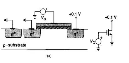
4. You can change the gain any way you want from 1 to millions. But in order to have some consistency, I recommend the following way that occurred to me today.
A_OL = 1. First set the smallest gain by writing "1" in the gain field and you will see that Vd = 500 mV (significant voltage error).
A_OL > 10. Then repeatedly press the "0" key (or hold the key) - the gain increases tenfold, and you can see how the op-amp input voltage Vd vigorously drops. To move in the opposite direction, press repeatedly (or hold) the backspace key. This way we mimic something like sliders in CircuitLab.
A_OL = 10e10. When you enter 10 zeros, the voltmeter shows zero.
Varying A_OL. Now let's do it fully automatically with the help of the CircuitLab DC sweep simulation by varying op-amp open-loop gain OA.A_OL. To see the most interesting first part of the graphs, in the schematic above, I have set a sequence of gains (1,2,3...10,20,30...100) as a second parameter; you can change it as you want. As you can see, the error op-amp input voltage rapidly decreases from 500 mV (gain of 1) to 10 mV (gain of 100).
Explanation
The simulator helped us to see the effect of the open-loop gain on the voltage error, but we need to explain what we saw; only then can we say that we have understood it.
Reversed amplifier. This experiment helped us to see something interesting in the op-amp behavior caused by the simple connection between its output and the inverting input - the op-amp itself changes (adjusts) its input voltage Vd to match its output voltage Vout, which in turn is set by the circuit input voltage Vin. It is as if the op-amp has been "reversed" - its output has become an input and the input has become an output... and it has become a kind of "attenuator" that reduces Vout to Vd A_OL times. Thus, the op-amp makes the difference between Vin and Vout negligible and Vout is almost equal to Vin.
Op-amp integrator. It is obvious that the op-amp that is "chained" by the negative feedback cannot act instantaneously when the curcuit input voltage Vin changes (see also a related answer of mine). Its "transition gain" A_tr = Vout/Vd is less than its open-loop gain A_OL and the op-amp needs some time to reach equilibrium when A_tr = A_OL. Only then Vout = Vin.
The three gains. So, my conclusion is that in total there are three gains: a temporary gain acting during the transition, an open-loop gain and a circuit gain of the op-amp follower. When the circuit input voltage Vin changes, in the first moment, the op-amp output voltage does not change. The transition gain is below 1 but it begins vigorously increasing and finally reaches the op-amp open-loop gain. Then the output voltage becomes (almost) equal to the input voltage.
"Follower man"
The best way to imagine what the op-amp is doing during the transition is to put ourselves in its place. That is why, I suggest you make, in the form of a fun game, a "follower man" in the likeness of the famous H&H "transistor man". But you will have to show a little more dexterity because CircuitLab is not suitable for such "frivolous" games:-)
Our "man-controlled follower" is extremely simple because, besides the man, it consists of only a variable source Vout and a sensitive voltmeter Vd acting as a null indicator; but as you will see from the experiment, it is almost perfect. Another interesting thing is that it was invented back in the 19th century when there were no op-amps.
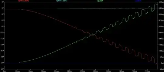
As you can see, the two voltages are connected in series and in reverse in a loop so their difference is applied to the voltmeter. The only problem is that you will need to work with two voltage sources at the same time - once setting the input voltage via Vin and then gradually adjusting the output voltage Vout equal to Vin.
- 13,593
- 1
- 17
- 48
Let me ask you a question. When you drive a car, whether around a curve, or along a straight road, what is the difference between your desired direction and the car's actual direction?
Another: when you adjust the temperature of your room to a comfortable level, eventually, what is the difference between your preferred temperature and the room's actual temperature?
The answer to both questions is zero. The car goes exactly where you want it to go (otherwise you crash), and the room's temperature is the same as the temperature you find comfortable.
In both cases, you have some desired state, or "output", in mind, and adjust things such that the actual state, or "output", is exactly that, with zero difference.
If the room's too hot, cool it down. If the car's turning too sharply to the left, adjust to turn less sharply. That's negative feedback, adjustment of things in a direction opposing its current "wrongness". In that way, it becomes just right.
An op-amp does the same. Negative feedback causes it to adjust its output in such a way as to minimise the difference between its two inputs; in other words, to make their difference zero. If you consider one input as a statement of where you desire the output to be, and the other input as a measure of the existing output state, the op-amp simply shifts its output in a direction that will reduce the difference between "actual state" and "desired state", until they are equal.
This concept allows us to make the statement that \$V_+ = V_-\$ whenever negative feedback is present for a op-amp, which makes the maths so much easier.
However, your concern seems to be about that difference of zero being impossible to multiply by anything, to get some non-zero output.
The truth is it isn't zero. It's just really really close to zero. And the gain of the op-amp is so big, that when multiplied by that very very small input difference, actually produces an appreciable output.
An example might help:
simulate this circuit – Schematic created using CircuitLab
See how the inverting input is not really equal to the other input at 0V? Well, that's what's really happening. The difference between the inputs is tiny, only 4 microamps negative, but when multiplied by the huge 1000000 open-loop gain of the op-amp, you get -4V out.
Still, the difference is very close to zero, and the approximation \$V_+ = V_-\$ is a very good one, most of the time.
"But:, you say, "for an ideal op-amp, the difference truly is zero, so how does that work?" Well, it doesn't. You are right to question the theory. The mathematics we are taught regarding an ideal op-amp is usually flawed, because the claim that it has infinite gain is not strictly true. The correct claim is that an ideal operational amplifier has gain approaching infinity, a critical distinction.
Consequently, with negative feedback we don't claim that the difference between the inputs is zero, we claim that the difference only approaches zero, that it's infinitesimally small.
It may seem pedantic, but by removing infinities and zeros from the algebra, questions like that do not arise. The algebra becomes consistent, and values stay well defined, and finite.
- 27,759
- 2
- 16
- 87
-
Exactly! This is the (human) way to understand how an op-amp works - transferring our living human ideas from all these analogies of life to the non-living electronic device. – Circuit fantasist Mar 17 '23 at 20:04
The voltage difference between inputs is zero because the op-amp is an active component that has external feedback between output and input.
If the voltages at inputs are different, then the op-amp will adjust the output until through the both inputs have equal voltage.
So it does not change how an ideal op-amp itself works. The difference between inverting and non-inverting circuit is really the circuit external to the op-amp, i.e. how the circuit arranges the input and feedback to an op-amp.
- 127,425
- 3
- 97
- 261
-
Your right and the rightness of your speech can be proven in some simple kcl equations but without them, the process is difficult to figure out by just looking and thinking (at least for me). – Sina M Mar 17 '23 at 07:14
-
Sina N - are you familiar with control theory? Here, we also have negative feedback - and it is the task of the summing junction (which compares input and signal feedback) to make the error signal as small as possible (depending on loop gain). In case of an opamp the differential input acts as a summing junction and the loop gain is pretty large (Aol app. 100 dB). – LvW Mar 17 '23 at 07:49
- An "ideal" op-amp has infinite open loop gain so, we can always say that the two input voltages are equal in a linear application with negative feedback.
- A more practical op-amp might have an open loop gain of 100,000 and, to get 1 volt at the output we need an input voltage difference of 10 μV.
- Given that a more practical op-amp might have offset errors bordering on 1 mV it's still reasonable to make the approximation that the difference between the two inputs is zero
- If you want to get all fussy about the math not being correct, then you are missing the point of virtual grounds and op-amps; they are imperfect but we can still treat them as perfect things providing we understand their (and our) limitations.
- 434,556
- 28
- 351
- 777

