3

Beginner to circuit building here. I tried to build the following toggle switch using one side of a TC4013BP [EDIT: I'm using a 9 V power supply, why did I write 12V? Sorry!]:

enter image description here

enter image description here

(I know, white wires with a white breadboard, great choice....)

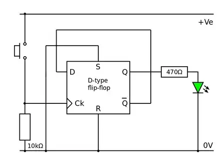
This is the original design:

enter image description here

(original plan here: https://pfnicholls.com/Electronics/Dtype.html)

I stuck it on a breadboard (picture above), put a 9 V across the high and low (as well as powering the chip on the same rails, as shown) The problem is that it doesn't toggle - the LED turns on when I push the switch, and then turns off again when I release it.

My understanding is that when I hit the clock, data gets sent to Q, and Q-not gets set to opposite that, ready for the next cycle. If we start at Q=0, hitting the clock turns the LED on (that happens in my circuit), and sets Q-not and data to low. I hit it again, and data (now low) gets sent to Q, turning off the LED.

I guess I don't understand what the voltage at Q-not is at the beginning, but still - the LED does light up when the switch is engaged, it just doesn't stay on when the clock turns off.

I think that's how the circuit works - is that correct?
cduston
  • 131
  • 3

3 Answers3

5

You're missing the power supply to the IC.

  • Ground to pin 7
  • 5 V to pin 16

When you press the switch, the supply voltage flows through the IC into the LED. When you release the switch, there is no longer a source of power, so the LED goes off.


However, as soon as you fix that, you'll come back to us and say: "When I press the switch, the LED ends up on or off in a random way, instead of alternating off and on."

We'll then tell you that the problem is that that switch produces a dozen or so pulses every time you press it, not a single pulse. It's called bouncing. Then we'll direct you to Stack Exchange posts about debouncing.

Davide Andrea
  • 16,164
  • 4
  • 33
  • 62
  • Appreciate the thought, but I think it's pretty clear the IC is being powered, right? From pins 7 and 14. – cduston Mar 17 '23 at 23:10
4

Switches will bounce, causing multiple clocks. You need to debounce the switch.

If you have a double-throw switch, you can use the same chip to debounce with a RS latch.

Or, you can use a Schmitt trigger IC. A CD40106 is compatible with your voltage levels.

schematic

simulate this circuit – Schematic created using CircuitLab

Mattman944
  • 13,638
  • 1
  • 19
  • 43
  • True. But that's not OP's problem. OP's problem is that they didn't wire a power supply to the IC. – Davide Andrea Mar 17 '23 at 02:16
  • 1
    @DavideAndrea: I did wire a power supply to the IC - I powered the upper and lower rails with a 9 V, and put both V_e/0 V in the diagram and V_DD/V_SS in the chip to them, in parallel. I agree that I don't think it's multiple clocks, since the behavior is predictable, but the IC is powered. Now maybe they should be separate power sources? – cduston Mar 17 '23 at 02:27
  • I have a double throw switch that is spring-loaded to be on by default, which I can push to momentarily turn on in the other setting (it's from a guitar pedal - is that called On-On?). So you're saying get rid of my current circuit (using data and clock) and use the first of your examples. I see that you can switch Q on and off with correct values of R and S, but I don't think that works with my switch. If default position is in your sketch (High S, low R), that's high Q...switch to high R, that's low Q, but when I let go the switch goes right back to High S, low R, right? – cduston Mar 17 '23 at 03:42
  • 1
    @cduston They don't need to be separate power sources. There seems to be confusion from some people since you didn't draw the power on the diagram (but you wrote you did). Maybe it would be sensible to draw them on the diagram – user253751 Mar 17 '23 at 10:08
  • 1
    " I did wire a power supply to the IC". Well, why did you not show it? Regardless, the fact is that the circuit behaves as if it is not powered. Do check that the power supply (positive _and_ negative) are indeed connected. – Davide Andrea Mar 17 '23 at 12:32
  • @DavideAndrea I did not include that, because I don't really know the proper way to do so. Since I'm using half of a dual IC, I didn't know how to indicate those extra pins in some kind of self-consistent way. How about this, I'll redraw the whole thing later today, with all the pins (unused as well), and maybe that will give us some clue about what's happening. Thanks! – cduston Mar 17 '23 at 13:37
3

What about power supply a rail bypass cap .Nothing is there.Try a 33 ohm resister in B + and a 100n ceramic cap across pin 7 and pin 14 of the chip.

Autistic
  • 14,235
  • 2
  • 27
  • 65
  • resistor makes no sense but a decoupling capacitor is never a bad idea – user253751 Mar 17 '23 at 10:09
  • @ user253751 .The resistor damps out possible resonances with power line inductances that could make voltage spikes at power up if the power is applied suddenly like a mechanical switch Also the resister forms a crude spike filter which is handy if the psu is a yukky flyback. .Also the resister keeps short circuit currents to a sane level . – Autistic Mar 17 '23 at 10:39
  • thanks for suggestion, I tried both 33 nF and 220 nF across the supply pins, no change to the behavior. – cduston Mar 17 '23 at 23:56