3

I'm trying to take the input from a microphone and use it to power an LED, so that it's off at ambient sound, and (the peak brightness) gets brighter with noise level. It's okay if it flickers, I'm just trying to get the peak voltage to be proportional to sound levels.

What I know: - The loudest sound I use causes the microphone to emit 80mV - The LED faintly lights at 1.8 V - The LED maxes out at 2.2 V - The transistor I'm using activates when V_be > 0.6 V

What I have:

schematic

simulate this circuit – Schematic created using CircuitLab

I tried to make a voltage divider so that the voltage between RC and RE was 1.8 volts, and 0.6 for R1 and R2. However, this doesn't work, simulated or on the breadboard. What am I doing wrong?

  • 4
    You show the microphone connected to a "ground" symbol, but you don't show any other node in the circuit also connected to ground. This makes it difficult figure out what your intent is. The circuit would probably work if you connect it to the junction of R2 and RE. – Dave Tweed Apr 17 '13 at 02:09
  • 'It' being the (currently) grounded end of the microphone? – Henry Swanson Apr 17 '13 at 02:15
  • 2
    The LED should probably be in series with Rc, rather than in series with the battery. – Peter Bennett Apr 17 '13 at 02:20
  • @HenrySwanson: Yes. – Dave Tweed Apr 17 '13 at 02:22
  • Alright, I've made the modifications that @DaveTweed and Peter Bennett mentioned, and now: the LED's current varies at 440Hz, from 3.84 to 4.61 mA, and the voltage at the LED and capacitor vary very little (~10 mV per cycle). The voltage at the emitter is low, at max 930 mV. Hopefully this is enough information for troubleshooting. :/ I can link the simulator I'm using, if that helps? – Henry Swanson Apr 17 '13 at 02:34
  • Now you need to adjust the transistor bias so that it is (just barely) cut off with no signal from the microphone. The emitter voltage should be no more than a few tens of mV in this state. Also, you might want to increase the values of the bias resistors by an order of magnitude or more, so as to not load the microphone so heavily. – Dave Tweed Apr 17 '13 at 11:54
  • The bias resistors are R1 and R2? And adjusting the transistor bias would be changing the ratio between R1 and R2, right? – Henry Swanson Apr 17 '13 at 13:10
  • sorry about that, i was a literal child when i wrote this question... haven't thought about this in years. in any case, now that i've got a better background with electronics, i've been able to understand the answers that were graciously given. much belated thanks :) – Henry Swanson Dec 21 '22 at 05:33

3 Answers3

6

I think a single transistor solution won't be good enough - you have to consider the standing DC currents when no microphone is present - these will likely still illuminate your LED and this is not what you want. Here's a circuit I designed many, many years ago and I've added a third transistor stage on to drive a LED: -

enter image description here

You might find it's a little too sensitive for your microphone but that can be reduced by increasing R3. It's output stage is designed to drive a 20mA LED hence the 390R resistor for R5. With no sound present the LED will be off.

The circuit; Q1 amplifies the input signal and Q2 rectifies the level converting AC signals into a DC level on its emitter. It's self-biasing and draws only a few micro amps when the mic is inactive. C2 smooths the rectified signal on Q2's emitter and this feeds Q3 which gives the signal enough grunt to drive the LED.

Andy aka
  • 434,556
  • 28
  • 351
  • 777
0

Besides the issue Dave Tweed commented on, there is the issue that your circuit modulates the current through the diode. Further, you must distinguish between the DC current and the AC (time varying) current.

First, you must solve the DC circuit by zeroing the microphone source. I calculate that the DC current through the transistor is roughly 4mA.

For this value of bias current, the AC transconductance of Q1 is roughly 150mS.

The input impedance of your CE amp is roughly 800 ohms which is quite low.

You don't specify what the output impedance of the microphone is but you must take that into account due to the low input impedance. For example, if your microphone is a "Hi-Z" microphone, much of the potential gain of your circuit will be lost due to voltage division.

This is about all that can be said without further details.

Alfred Centauri
  • 26,502
  • 1
  • 25
  • 63
  • How would I measure the impedance of the microphone? What do you mean by 'zeroing the microphone source'? Yes, the current through the diode is 4 mA. (Sorry I'm asking so many questions, the only electronics things I know are the boring textbooks laws, and I'm finding them hard to apply to real circuits) – Henry Swanson Apr 17 '13 at 02:41
  • @HenrySwanson, if you don't have the microphone data sheet, it is possible to measure the impedance. Simply measure the output open circuit and then connect a variable resistor to the output. Under the same acoustic conditions, vary the resistor until the output is 1/2 the open circuit value. Then, measure the resistance of the variable resistor. This value will be the approximate value of the output resistance of the microphone. – Alfred Centauri Apr 17 '13 at 02:46
  • Is output voltage or current in this case? (I'm thinking voltage but I want to be sure) – Henry Swanson Apr 17 '13 at 02:48
  • @HenrySwanson, voltage, yes. Essentially, you're using voltage division to determine the output impedance. To be sure, we're talking about disconnecting the microphone from your amplifier for these measurements. – Alfred Centauri Apr 17 '13 at 02:49
  • Okay, I understood that! The mic is at school right now, but I can do the measurements tomorrow morning. Anything else I should measure? – Henry Swanson Apr 17 '13 at 02:57
  • @HenrySwanson, I would measure the current required to adequately illuminate the LED. – Alfred Centauri Apr 17 '13 at 03:08
  • let us [continue this discussion in chat](http://chat.stackexchange.com/rooms/8386/discussion-between-henry-swanson-and-alfred-centauri) – Henry Swanson Apr 17 '13 at 15:33
0

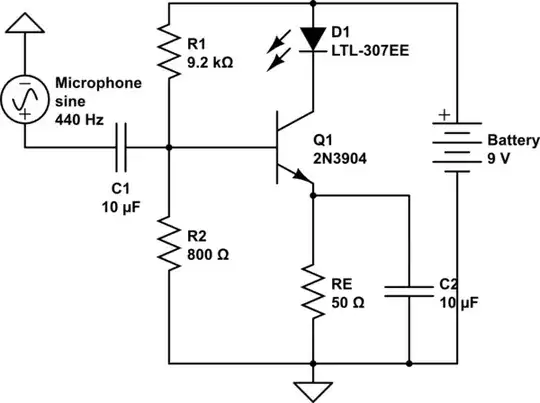
Your amplifier is not a common emitter, but rather an emitter follower. That is why it doesn't work: it does not amplify voltage. The small voltage swing of the microphone is placed across the emitter resistor + LED. The only thing that the circuit does is to provide the current delivery.

By the way, it's not realistic to model a microphone as a voltage source, because it has internal impedance. This matters because unlike a perfect voltage source, a real mic cannot impress its full voltage onto the input stage. Due to the low impedance of these designs, they can only work with a low impedance microphone (two to three digit ohms).

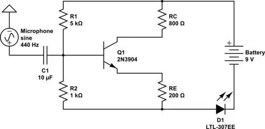
Try this small modification to your circuit. This is a common emitter. The load is on the collector side. I fiddled with the values so that the LED current oscillates between close to 0 to as high as 3 mA. Try a time-domain simulation up to 0.005 seconds in 0.0001 second increments, watching the diode current.

schematic

simulate this circuit – Schematic created using CircuitLab

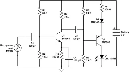
Two-stage version based on a continuation of your idea. Here we have separate voltage amplification stage followed by a PNP output stage to drive the current to the LED. This one turns the positive cycles of your wave into 20 mA current peaks through the LED. The LED is cut off on negative cycles:

schematic

simulate this circuit

I have increased the coupling capacitors because the impedances are quite low in the circuit. The D4 diode just provides a small level shift. Without it, the voltage swing going into Q2 doesn't quite reach high enough toward the 9V rail to cut the transistor off, leaving a quiescent current through the LED. I wanted it shut off.

Kaz
  • 19,838
  • 1
  • 39
  • 82