4

I have a certain electrical problem with me that I'm unable to figure it out. I need to pass 10 A current through a 2.3 Ω nichrome wire to heat it up using a 4.2V Li-ion battery with a 70-150 C discharge rate. I currently have the following MOSFETs with me:

IRLB8721 (NMOS)
IRF9530 (PMOS)
IRF9640 (PMOS)
IRF9540 (PMOS)

The circuit I'm trying to emulate with a current source (and working) is attached.
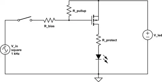
Circuit with 10A current source and NMOS as a switch 10 A current source with an NMOS acting as a switch

I tried many approaches like using a current mirror to pass the 10 A through the load, or simply replacing the current source with a PMOS to bias it at 10 A and allow it to pass through the load (all of these simulations are done in LTspice) and none of these approaches seems to work.

Also my concern is that 10 A passing through 0.5 Ω resistance will need 23 V while I'm limited to a 4.2 V source.

How can this limitation be overcome? Through the use of current amplifiers or any other thing, and what would the circuit look like?

Edit: I made a mistake in calculating the actual resistance of nichrome wire. It's actually 0.5-0.8 Ω. The internal resistance of the meter was calculated to be around 2 Ω. Also the battery I'm using is from this website.

I also tried a boost converter that I had lying around. I calculated the open-circuit voltage to be around 12 V and then when I used it as a power source, it immediately dropped to 5-6 V and was hardly drawing 1 A of current through the load of 0.5 Ω. I even bumped the open-circuit voltage up to 24 V and the result was still the same.

The objective is to heat the nichrome wire as fast as possible. I've used the 10 A current source from the power supply (the circuit I've already shown). The wire heats up fast with that. So all I'm trying to do is replace that current source with an equivalent circuit. Now I'm not sure exactly what I'm missing here or what I'm doing wrong here. I had the power supply giving me 10 A and 3.7 V.

ocrdu
  • 8,705
  • 21
  • 30
  • 42
Dian Basit
  • 41
  • 3
  • 5
    You will need to step up your voltage, there is no way around it. There are boost converters that can help. – Eugene Sh. Mar 14 '23 at 18:09
  • 2
    start by connecting the nichrome wire directly across the battery ... that way you have no semiconductor components causing a distraction in your head – jsotola Mar 14 '23 at 18:57
  • You've provided the rated discharge rate of the battery, but that's not very useful without knowing the **battery capacity**. Please *edit* the question to include that information, and then flag this comment as "No longer needed". – Kuba hasn't forgotten Monica Mar 14 '23 at 19:02
  • 3
    Also, this question is a rather typical example of an XY problem. You think the problem is "which mosfet should I use", but that's not a problem at all, and you won't be needing any discrete mosfets at all... – Kuba hasn't forgotten Monica Mar 14 '23 at 19:11
  • _"I need to pass 10A current through a 2.3 ohms nichrome wire to heat it up using **4.2V LiPo battery with 70-150C discharge rate**"_ - why? – Bruce Abbott Mar 14 '23 at 19:27
  • 5
    Cut that nichrome wire into four equal pieces, connect them in parallel, and that will be 2.3Ω/4 = 0.575Ω. 3.6V/0.575Ω = 6.26A, 6.26A*3.6V=22.54W. Search for those MOSFET datasheets and see what their Vgsth or gate threshold voltage is - they might need 6V or more at the gate to even start turning "on." – rdtsc Mar 14 '23 at 19:36
  • @Kubahasn'tforgottenMonica the battery capacity is 650 mAh. – Dian Basit Mar 14 '23 at 21:33
  • I'm gonna try boost converter since that is the common answer I'm seeing. Thank you for all the quick response. Appreciate it – Dian Basit Mar 14 '23 at 21:34
  • @rtdsc: The resulting resistance will be < \$\frac{1}{4^2}\$ the original. Accounting for some length "lost" due to "connecting", three parts for 2,3/9 Ω may be closer to the resistance to draw 10 A from a heavily loaded Li cell. – greybeard Mar 15 '23 at 04:20
  • @DianBasit If you can manage it, it's much cheaper to redesign the nichrome wire. If the wire is fixed in stone, it might still be easier to get a different battery with the needed voltage. Of course, if you are only making one of it, you can afford to be a little inefficient with cost if you want, as well as using your spare parts lying around. – user253751 Mar 15 '23 at 19:51
  • Dian, this all makes no sense, the 10A have nothing to do with your objective! if you directly connect the 0.5Ω wire to your battery, you'll probably get more current than 10A (at least for a short duration), before your resistance starts to increase due to the wire heating up. Do you **really** want to "heat the nichrome wire as fast as possible", or does "heat it up to a specific temperature within a specific time" suffice? These are different things, and "as fast as possible" is a hard optimization problem, which needs your DC/DC converter to change its voltage with wire temperature. – Marcus Müller Mar 15 '23 at 19:52
  • and as @user253751 says, if you just "half" the wire and put two 0.25 Ω pieces in parallel, you will instantly get much more heat, no extra converter, semiconductors,… needed – Marcus Müller Mar 15 '23 at 19:53
  • @MarcusMüller, the objective is to heat it (so that it turns yellow, which I presume is 1500 celcius) as quickly as possible. The experiment that I did with 10A(max current that my power supply could provide) with a power supply with N-MOS acting as a switch did the job. Now I'm trying to replace that source with an equivalent circuit. This is my objective in general. Also yes, I haven't tried this approach yet, though overall I can see that current would increase but doesn't that mean, through branching current, would split and each wire would get roughly the same current? – Dian Basit Mar 15 '23 at 20:05
  • yes, but now you're dissipating more power in total, because they are all in parallel.put them in vicinity of each other, and they will get hot, very quickly. – Marcus Müller Mar 15 '23 at 20:14
  • If you get 10 amps at 3.7 volts with your power supply, the nichrome wire must be 0.37 ohms. You can't measure such a low resistance with any accuracy using a DMM with two leads. It requires a high current (like your 10A), or a four lead Kelvin connection. And please update your question title and text for the correct resistance. – PStechPaul Mar 16 '23 at 00:56
  • Using parallel wire strands and using them next to each other draws more current from battery and it also heats up other strand of wire quickly. This did the trick thanks! – Dian Basit Mar 21 '23 at 18:35

4 Answers4

9

There is nothing to figure out, because it is not possible.

A 2.3 ohm load on a 4.2 V battery will draw a current of 1.8 A.

And the battery is almost never that full to have 4.2 V, typical battery has a nominal voltage of 3.6, so it can be less too.

You would need to have multiple batteries in series or a boost converter to provide larger voltage, or multiple smaller resistances in parallel as load.

In any way, the battery would have to be rated to provide the required 10A without damaging or overheating, because that is a lot of current. Just make sure your battery can handle it.

To use a boost converter, providing 10A at 23V into a 2.3 ohm load means 230 watts, and so the battery would have to provide about 55 amps at 4.2V.

Justme
  • 127,425
  • 3
  • 97
  • 261
  • Probably need to account for the internal resistance, as well. – Scott Seidman Mar 14 '23 at 18:48
  • @ScottSeidman I have no clue what battery that is or what kind of wiring it has but 10A current sounds very unrealistic if not just impossible. – Justme Mar 14 '23 at 18:55
  • Thank you for a quick response! Overall response I'm seeing is the use of boost converter. I'll try that. – Dian Basit Mar 14 '23 at 21:24
  • 5
    @DianBasit: Please don't burn down your house / building by pulling too much current from your battery. Pulling even more power at the same voltage means even more current. Your battery will need to be pretty large to handle a 230W load, or more since the boost converter won't be perfectly efficient. I worry that since you didn't realize that 4.2V can't push 10A through 2.3 ohms, you might be missing other simple calculations that could lead to safety problems if you hook up something that can pull a lot more current from your battery. Test outdoors if possible, battery fire is serious. – Peter Cordes Mar 15 '23 at 08:21
  • 3
    @DianBasit whatever problem you're trying to solve here by putting 10 A through your 2.3 ohm nichrome wire, taking that power from a single lithium battery: I'm almost certain your missing something. As multiple engineers have told you now, you're requiring your battery to provide 250 W in power. That doesn't usually go well with lithium batteries as long as you do not add temperature control and you probably need to change your approach very drastically to make this even theoretically possible. – Marcus Müller Mar 15 '23 at 09:26
  • Yes, thank you for your response. Yes, certainly what I was asking was a little unrealistic, and was wondering if it's possible. However, I also made a mistake in the actual resistance of the wire. I didn't take into account of internal resistance of the meter. The actual resistance of the wire is 0.5 ohms. I mentioned this in my original post above with additional information. – Dian Basit Mar 15 '23 at 14:55
  • 1
    @PeterCordes Yes I'm taking super precaution in this and definitely not peforming this indoor or at home. Thank you for your concern. Appreciate it. – Dian Basit Mar 15 '23 at 14:56
  • @MarcusMüller You might be surprised about the capabilities of lithium batteries - but yes, it is important to check the numbers first. A li-po battery that can deliver 250 watts can be held comfortably in one hand, and is probably smaller than the one in your laptop. – user253751 Mar 15 '23 at 19:22
  • @MarcusMüller in fact the battery that Dian already picked out weighs only 20 grams, 53x31x7mm (less than half the size of a credit card) and is rated for 45 amp discharge and 90 amp peak! that will discharge the whole battery from full to empty in under a minute *and it's designed for that*. See, these batteries are absolutely crazy. – user253751 Mar 15 '23 at 19:25
  • @user253751 no question asked there – high-current batteries are a thing; but note that you can discharge a 100 C battery in the course of 1/100 of an hour. And as Dian now realizes, a DC/DC with a 10 A output is not that trivial to come by. – Marcus Müller Mar 15 '23 at 19:47
  • 1
    @user253751 see my answer. The battery product page **must** be bogus, or dangerous, or both. That's a 2A rated connector on that battery, and the whole device weighs 20 g. I have my serious doubts about the 140 C rating. – Marcus Müller Mar 15 '23 at 20:13
4

That's a 1/4kW heater, and the 2.3Ω resistance on the nichrome wire is the cold resistance. We must assume the wire will likely be quite a bit warmer though, as will be the wire that supply it, so its resistance when warm can be let's say 3..4Ω. So we need not a 3.7V supply, but something that can push up to 10A into the load, at a voltage of 24V (cold) to 36-40V (hot), to have ample margin.

The step-up/boost source should be configured for constant power operation, not for constant 10A current. As the wire gets hotter, it'll be outputting the same thermal power at several amps less than the cold current of 10A.

In any case, you're looking at a rather stout boost constant-current converter, and an additional control loop that adjusts the current to be inversely proportional to voltage, to maintain the constant power - since that's presumably what you want: a constant thermal power.

Most any boost converter will have an on-off control logic input, so you don't need to worry about discrete mosfets for that.

If you want/need something else, please edit the question to provide what the exact application is this nichrome wire used in.

  • Thank you for a detailed explanation! I'll try this boost converter approach. Turns out my requirement were unrealistic. I was wondering if the requirement could be matched based on mosfet. I'll try this approach! – Dian Basit Mar 14 '23 at 21:25
  • 1
    (@DianBasit You didn't spell out your requirement - please clarify in the question: is it to dissipate 230 W?) – greybeard Mar 15 '23 at 04:22
  • @greybeard I just mentioned the update in the original post above. No, the idea is not to dissipate 230W but to heat the nichrome wire as fast as possible. Just like how vape technology heats up the coil as fast as possible. – Dian Basit Mar 15 '23 at 14:51
  • @DianBasit then, where does the number 10A come from? You want as many amps as possible, why limit yourself to 10? – user253751 Mar 15 '23 at 19:23
  • @user253751 You're right I can do as many amps as I can. It's just the power supply I was using had a limit of 10A. But if I can do more than 10A with circuitry I would definitely go for that. That means the wire would heat up faster which works for my application. – Dian Basit Mar 15 '23 at 19:53
2

Dian, this all makes no sense, the 10A have nothing to do with your objective! if you directly connect the 0.5Ω wire to your battery, you'll probably get more current than 10A (at least for a short duration), before your resistance starts to increase due to the wire heating up. Do you really want to "heat the nichrome wire as fast as possible", or does "heat it up to a specific temperature within a specific time" suffice?

These are different things, and "as fast as possible" is a hard optimization problem, which needs your DC/DC converter to change its voltage with wire temperature.

So, I'll go with "if it gets really hot really fast, I'm happy". Let's optimize for that!

If the maximum burst discharge rating is correct (and I have doubts when it comes to websites selling batteries without extensive datasheets), then 140 C means you can discharge your battery in 1/140 of an hour, so that's a maximum current of 650 mA · 140 = 91 A.

Assuming that under that load, the battery still supplies 2 V, that means it has an effective internal resistance of 17 mΩ (and not the 1.7 mΩ that the description falsely claims).

Therefore, a 17 mΩ load would maximize the power you draw from the battery. That would be, roughly, 1/25 of your current nichrome wire resistance of 0.5 Ω.

That's nice, because it means all you have to do is cut up your wire into 5 equally long parts, and put them in parallel (with a very good contact).

Then you'll be converting roughly 200 W (Because of 2 V that the battery still can do under load, and the 90 A it can supply, and because exact numbers are hard here when a milliohm makes a large difference) to heat in the wire.

Note that this can't go on for long. When the internal battery resistance is as high as the external resistor, you're achieving maximum power transfer, but you're also converting roughly the same amount of power to heat inside the battery. Also, the wires on that product photo do not at all look like they are capable of 90A. Seriously.

So, I really can't trust that product page. Even 17 mΩ seems pretty unlikely, considering a mass of barely 20 g, and these cables.

Even going with the more conservative 70 C, that's still 45 A. The JST-PH-2.0 connector that this battery pack has is rated for 2A! It'll melt, quickly, under 45 A load. At 90A load, it'll possibly catch fire. (again, won't happen, your wires are far too tiny and have multiple mΩ of resistance themselves.)

Marcus Müller
  • 88,280
  • 5
  • 131
  • 237
0

4.2v ÷ 0.5ohms = 8.4A = 35W. That will be enough to heat your wire in a few seconds

Mosfet N channel IRLB3034 in lowside configuration, like your draw

Voltage Spike
  • 75,799
  • 36
  • 80
  • 208
Diego
  • 21
  • 2