This is a tough question to answer without referring to lots of stuff like Kirchhoff's laws, and Ohm's law, and impedance and wotnot, but I'll give it a shot. Forgive me if any of this seems obvious, I have no idea what you don't know.
Let's start with a few facts about the diode.
The diode does the trick of appearing to be one thing under certain circumstances, and another very different thing under other circumstances. What I am about to say is a very rough and approximate model, but it's close enough for this answer. If the cathode (negative) end of the diode has a higher potential (voltage level) than the anode, then the diode acts as if it's not there. There will be no connection inside the diode between its two terminals. It might as well be air.
If, however, the potential of the anode rises to equal, or tries to exceed its cathode's potential, it becomes a very low resistance between its two terminals, like a wire, like a short circuit (not strictly true, but close enough). This "wire" acts to join the two ends together, just like a wire, which brings the potentials together, to equalise them. In becoming a really good conductor, it is preventing the two ends from having different potentials.
Then, when something on the anode side tries to raise the anode potential above whatever's on the cathode side, or something on the cathode side tries to lower cathode potential below the anode, it becomes a tug-of-war between the systems on either side, because the diode literally joins the opposing systems together.
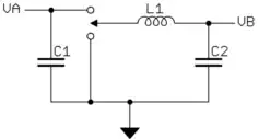
I'll redraw your circuit with some annotations to help with the explanation:
simulate this circuit – Schematic created using CircuitLab
What happens if the potential at A, \$V_A\$ is greater than the potential \$V_B\$ at B? In this state the diode's anode is higher in potential, and the tug of war is on. Who will win? The anode wins, because the purpose of a voltage source (in this case, V1) is to impose a potential difference no matter what. It can be likened an immovable object, firmly attached to immovable ground, with enough "strength" to overcome any attempt to alter that potential difference.
The diode's anode potential, \$V_A\$, is always going to win in any battle with something on the cathode side. If the team on the cathode side is trying to lower cathode potential \$V_B\$, to some value less than \$V_A\$, it will lose, and B is stuck at \$V_B = V_A\$.
You see that if \$V_A\$ rises, and circuitry on the B side is trying to "pull" or "set" \$V_B\$ to some lower value, then \$V_B\$ gets "dragged" upwards too, in spite of team-B's efforts. The circuit looks like this:

simulate this circuit
When team B is trying to raise \$V_B\$, though, things are different. With \$V_B > V_A\$ the diode's behaviour changes to that of literally disconnecting A-side from B-side, cutting the tug-of-war rope.
The circuit becomes:
simulate this circuit
In this situation team B is able to set whatever potential \$V_B\$ it likes, so long as it's not lower than \$V_A\$.
Now let's talk about the op-amp.
To the outside world, the inputs to an op-amp appear (ideally) to be unconnected to anything else inside that IC. From the outside, that pin on the IC is just a piece of metal. Clearly, that's not true, because the op-amp is somehow able to "know" the potential of that pin, but for all intents and purposes, it is safe for us to say the pin is "floating", all alone, with nothing to define ("set") its potential (voltage level).
Given that the non-inverting input, node B, isn't being pulled or pushed anywhere, because it's not even connected to anything except the diode, everything I've just said is moot! I mean, what even is the potential at B, considering no-one on team-B is in any control of it?
I would hazard a guess, that since your output C seems to be stuck near one of the supply rail potentials, and is unrelated to A, that rail must be the positive one, since that's the case when \$V_B > V_A\$. If it were the other way around, the diode would be "on", and you'd see some version of signal A at node C.
The problem you have is that in that last circuit above, there's nothing to set the potential of node B! Node B is literally free to set its own potential, as long as it's above A. Let me make another guess; if you touched that non-inverting pin with your finger, you'd see the output at C flapping up and down wildy, as your own body couples the noise of the entire universe onto that pin, because there's nobody else around to say otherwise! Read my answer to the question "Has anyone measured what a high-impedance pin looks like?", to understand this concept.
To answer your question directly, the reason the diode causes the behaviour you observed, is not really due to the diode, it's more a result of the idiosyncrasies of the particular op-amp you use under the condition where its non-inverting input is effectively floating.
We know that team B can win the battle for control of node B when it "pulls up" beyond A, but it never does this. In its current configuration, no member of team B ever pulls or pushes B anywhere. How do we prevent this state where node B is "floating"? One way:
simulate this circuit
A new member R1 is part of team B, now, gently tugging node B towards zero volts potential. Ultimately team B loses, if ever \$V_A\$ rises above zero, but wins otherwise. Node B is never floating, and will not suffer the fate described in that answer I linked to.
Now \$V_B=V_A\$ when \$V_A > 0\$, but \$V_B=0V\$ when \$V_A < 0\$.
If I put a sinusoidal source to control \$V_A\$, as you did, we can simulate this:
The input, \$V_A\$, is blue, and \$V_B\$ is shown in orange. This is a half-wave rectifier.
The moral of this whole story is: never create a situation in which an input may be "floating", unless you know that it's safe to do so. For an op-amp it is usually not safe to do so.
